


 17 / 50

ADVANCED MATERIALS & PROCESSES •
JULY 2014
17
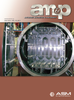
formity during a brazing cycle is +/- 5°F (3°C) of set point.
Aluminum brazing has a very narrow window of accept-
able brazing temperatures. The governing rule for alu-
minum brazing is that the filler metal must liquidize before
the base metal reaches its solidus temperature. This tem-
perature difference may be as small as 10°-18°F (5°-10°C).
Figure 5 shows the small process window available for alu-
minum brazing. For example, a base metal 6061 alloy will
have a solidus temperature of 1099°F (593°C) and a liquidus
temperature of 1206°F (652°C). The brazing temperature
range would be 1049°-1085°F (565°-585°C) depending on
the filler metal used.
Using a heating step at a soak temperature just below
the solidus point of the filler metal ensures that all the parts
and joints to be brazed reach the correct temperature at
approximately the same time. At this time, the ramp to
brazing temperature starts, filler metal begins to melt, and
capillary wetting of the braze joints occurs.
The time duration of braze temperature must be kept
to a minimum as melted filler metal is vaporizing in the
deep vacuum while trying to wet the braze joints. Too
much loss of filler metal to vaporization will result in poor
joint wetting and subsequent loss of joint strength and seal-
ing ability. After the brazing temperature soak duration is
complete, an immediate vacuum cooling cycle follows,
which solidifies the filler metal in the braze joints and stops
material vaporization.
The type of precise temperature control and uniformity
needed for VAB is achieved through the use of several
heating control zones around the parts while at the same
time maintaining the surface temperatures of the heating
elements as near to the part temperature as possible. A
large delta in temperature between the heating elements
and the parts would result in overheating of the parts’ sur-
face, possibly above the solidus temperature for the mate-
rial as the filler metal begins to melt.
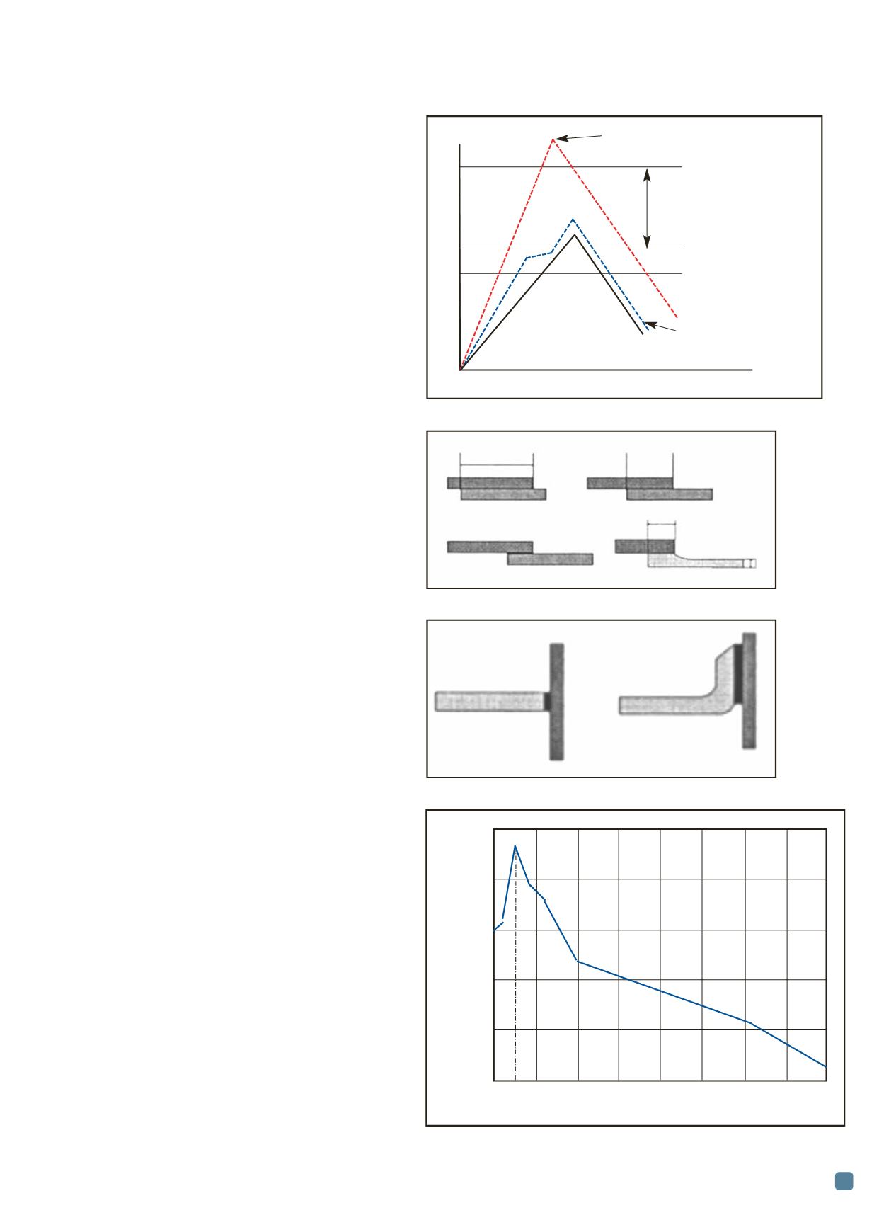
Braze joint fundamentals
Figures 6 and 7 show typical braze joints used in alu-
minum component construction. In general, the difference
between the favorable and unfavorable types of joints is the
amount of overlapping that results in good braze joints. A
stronger braze joint has a large surface area wetted by the
filler material. Too much overlapping is detrimental to the
joint because the filler material will not cover the entire
surface when it flows into the joint.
Braze joint strength is dependent on two primary me-
chanical characteristics: Joint wetted surface area and the size
of the gap intowhich the fillermetal flows. In Figs. 6 and 7, im-
proved joint surface area characteristics are shown. Figure 8
illustrates the importance of a proper joint gap.
Gaps between 0.003-0.008 in. (0.08-0.2mm) work best for
vacuum furnace brazing. Joint gaps are controlled by theman-
ufacturing tolerances of the parts to be brazed and by proper
clamping (pre-loading) of the part assemblies to be brazed.
Fixturing and cleaning parts
Part assemblies must be fixtured properly for brazing
Fig. 5 —
Temperature vs. brazing cycle steps.
Fig. 6 —
Lap joints
[2]
.
Fig. 7 —
T joints
[2]
.
Fig. 8 —
Braze joint strength vs. joint gap
[3]
.
Temperature
Time
Poor temperature control
Heat damage occurs
Process
window
Brazing alloy flows
Magnesium vaporization
Pattern that must develop
Unfavorable
Favorable
>6 t
3-6 t
t
t
4 t
Unfavorable
Favorable
0.003 0.006 0.009 0.12 0.15 0.18 0.21 0.24
Joint thickness, in.
Tensile strength, psi
140,000
120,000
100,000
80,000
60,000
40,000