


 19 / 82

A D V A N C E D
M A T E R I A L S
&
P R O C E S S E S |
N O V E M B E R / D E C E M B E R
2 0 1 6
1 9
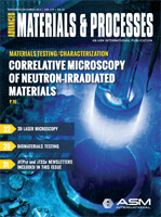
Fig. 2 —
(a) Raw SANS diffractogram for Fe-18Cr-2.9Al alloy, irradiated to 13.8 dpa at 341
°
C.
(b) Final SANS scattering intensity curve, combining data from three distinct detector config-
urations, and example fit of analytical model to the data.
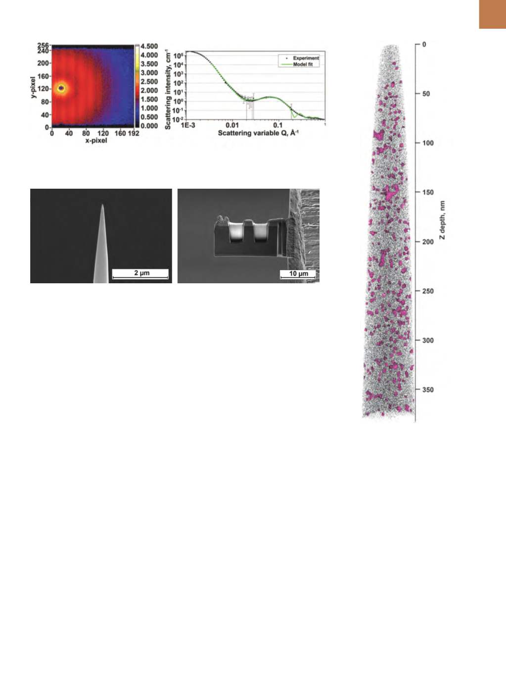
Fig. 3 —
SEMmicrographs of representative Fe-Cr-Al specimens prepared for (a) APT analysis,
and (b) TEM and STEM analysis.
Fig. 4 —
Atomprobe reconstruction
showing precipitate microstructure in Fe-
15Cr-3.9Al alloy, irradiated to 7 dpa at 320°C.
Precipitates are displayed using 34 at.%Cr
concentration isosurfaces (purple) with 2%
of total matrix Fe atoms shown (black).
a diffractogram for the Fe-18Cr-2.9Al
specimen irradiated to 13.8 dpa at 340°C
is shown in Fig. 2a, in which the precip-
itate signal manifests as a red-orange
contrast ring around the central zero-
beam (black contrast). Radial reduction
of these diffractograms to one-dimen-
sional curves allows analytical models
to be fit to the data, from which bulk-
averaged precipitate morphology infor-
mation can be extracted (Fig. 2b).
Sections from the remaining
half-tensile specimens opposite the
strained neck were cut using a low-
speed saw in the hot cells and shipped
to the Low Activation Materials Devel-
opment & Analysis (LAMDA) facility
at ORNL for FIB sample preparation.
LAMDA is a specialized facility designed
for state-of-the-art characterization of
low-radiological threat fuel and metal-
lic specimens
[6]
. Much less material is
required for FIB sample preparation
and subsequent analyses compared
to SANS, and the volume reduction
in the hot cell was sufficient to allow
for out-of-cell hand polishing of speci-
mens in LAMDA using standard metal-
lographic techniques with appropriate
personal protective equipment (PPE)
and dosimetry. Polished specimens
were then installed in a remotely-
operated FEI Quanta 3D Dual-Beam FIB
that is housed in a lead-lined room in
order to shield personnel from radiation
exposure. Operators of FIB equipment
are specially trained to handle the radio-
logical samples and a focus is placed on
efficient loading practices to minimize
exposure to the radioactive specimens.
Standard lift-out techniques
[7]
were
then used to prepare microtip needles
for APT analyses and lamellae for scan-
ning transmission electron microscopy
(STEM) investigations, examples of
which are shown in Fig. 3.
APT investigations allowed for an
atomic-scale study of individual pre-
cipitate composition and morphology
within a very small analysis volume.
Data collection was performed using
the Cameca Instruments Local Elec-
trode Atom Probe (LEAP) 4000X HR at
either the Center for Nanophase Mate-
rials Sciences (CNMS) at ORNL or at the
Center for Advanced Energy Studies
(CAES) at INL. Both facilities are capa-
ble of handling radiological samples,
but the significant volume reduction
(< 100
μ
m
3
on a single APTmicrotip cou-
pon) promotes ease of handling when
working at these laboratories. A repre-
sentative reconstruction of a Fe-15Cr-
3.9Al specimen irradiated to 7 dpa at
320°C is shown in Fig. 4. APT results
reveal that Al additions appear to
reduce the Cr content of precipitates
when compared to binary Fe-Cr alloys
[8]
,
and the observed precipitate morphol-
ogy trends are in agreement with those
seen in the SANS study, validating the
(a)
(b)
(a)
(b)