


 18 / 82

A D V A N C E D M A T E R I A L S & P R O C E S S E S | N O V E M B E R / D E C E M B E R 2 0 1 6
1 8
designing a nuclear-grade Fe-Cr-Al alloy
for LWR cladding applications.
To this end, neutron irradiation
and PIE analysis studies were per-
formed on four Fe-Cr-Al model alloys
with nominal compositions ranging
from 10-18 wt% Cr and 2.9-4.8 wt% Al.
Alloy compositions, as determined by
inductively coupled plasma optical
emission spectroscopy (ICP-OES), are
shown in Table 1. These materials were
machined into SS-J2 sub-sized tensile
specimens
[5]
and irradiated in HFIR to
various nominal damage doses up to
13.8 displacements per atom (dpa)
at a target temperature of 320
°
C, cor-
responding to a maximum exposure
time of approximately 4900 hrs. Dpa
commonly describes radiation damage
and is defined as the average number
of times an atom is displaced from a
lattice site for a given fluence of ener-
getic particles. Dpa is calculated based
on the fluence and energy spectrum
of incident particles for a given mate-
rial. The specimens in the 13.8 dpa
condition are expected to provide a
reasonable approximation of material
properties and microstructure at the
end of the typical LWR fuel cladding
lifetime. Details of final irradiation con-
ditions are shown in Table 2.
Following irradiation, an assess-
ment of tensile behavior was performed
using room temperature and elevated
temperature tensile testing with sub-
sequent scanning electron microscopy
(SEM) fracture surface analysis in-cell
at the Irradiated Materials Examination
and Testing (IMET) Hot Cell Facility at
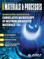
ORNL. Fractographs for a low- and high-
dose condition of the Fe-18Cr-2.9Al fol-
lowing room temperature tensile tests
demonstrate clear differences in speci-
men failure mode (Fig. 1a-b), with typ-
ical dimple ductile fracture observed at
early-life doses transitioning to brittle,
transgranular cleavage fracture at end-
of-life doses. Tensile tests performed at
320°C after irradiation demonstrated
ductile failure mechanisms in all dose
conditions studied (Fig. 1c-d).
Broken half-tensile heads from
each material condition were then pre-
pared, packaged for on-road shipping,
and shipped to the general purpose
small-angle neutron scattering (SANS)
beamline at ORNL for diffraction-based
analysis of nanoscale
α
ʹ precipitates in
the microstructure. SANS is a nonde-
structive analysis technique in which
an incident beam of neutrons is elas-
tically scattered by interactions with
nuclei or with the magnetic moment of
unpaired electrons. Bulk samples used
here (volume ~8 mm
3
) pose a signifi-
cant radiological threat, so special care
is taken during SANS investigations to
minimize user interaction. These larger
specimens are necessary in order to
fit the 4-mm-diameter aperture sizes
and allow for sufficient scattering to
maintain an adequate signal-to-noise
ratio in the SANS data. Two dimen-
sional diffractograms were collected
at room temperature at three different
detector configurations. An example of
TABLE 1
—
Fe-Cr-Al MODEL ALLOY COMPOSITIONS
INVESTIGATED IN THIS RESEARCH
Alloy
Fe Cr
Al
Y
C
Si
Fe-10Cr-4.8Al
wt% bal.
10.01 4.78 0.038 0.005 <0.01
Fe-12Cr-4.2Al
wt% bal.
11.96 4.22 0.027 0.005 0.01
Fe-15Cr-3.9Al
wt% bal.
15.03 3.92 0.035 0.005 0.01
Fe-18Cr-2.9Al
wt% bal.
17.51 2.93 0.017 0.005 <0.01
*S, O, N, and P contents at or below 10 ppm.
TABLE 2
—
SUMMARY OF Fe-Cr-Al ALLOY CAPSULE IRRADIATION CONDITIONS
Capsule ID
Exposure
time
(hours)
Neutron flux
(n/cm
2
s)
E > 0.1 MeV
Neutron fluence
(n/cm
2
)
E > 0.1 MeV
Dose rate
(dps/s)
Dose
(dpa)
Irradiation
temperature
(°C)
FCAY-01
120
8.54 × 10
14
3.69 × 10
20
7.7 × 10
-7
0.3
334.5 ± 0.6
FCAY-02
301
8.54 × 10
14
9.25 × 10
20
7.7 × 10
-7
0.8
355.1 ± 3.4
FCAY-03
614
8.84 × 10
14
1.95 × 10
21
8.1 × 10
-7
1.8
381.9 ± 5.4
FCAY-04
2456
8.74 × 10
14
7.73 × 10
21
7.9 × 10
-7
7.0
319.9 ± 12.7
FCAY-05
4914
8.74 × 10
14
1.55 × 10
22
7.8 × 10
-7
13.8
340.5 ± 25.7
Fig. 1 —
Comparison of fracture surfaces for Fe-18Cr-2.9Al alloy irradiated to 1.8 dpa (early life)
and 13.8 dpa (near end-of-life) conditions.
(a)
(b)
(c)
(d)