


 22 / 62

A D V A N C E D M A T E R I A L S & P R O C E S S E S | M A R C H 2 0 1 6
2 2
using a test specimen with a short un-
supported gauge length and using a lat-
eral support along the specimen length.
There are several different compression
test methods and associated fixtures
in widespread use that employ differ-
ent methods of load introduction and
anti-buckling. All composite compres-
sion fixtures are required to have ex-
cellent axial alignment and high lateral
stiffness in order to prevent the large
lateral loads that can be generated
during the test and cause specimen
bending. Most compression test meth-
ods require specimen bending to be
monitored and set a limit for maximum
allowable bending during a test.
Shear properties for design data-
bases are generally determined using
a V-notch specimen subjected to shear
loading across the V-notch using either
ASTM D5379 (Iosipescu) or ASTM D7078
test fixtures. Specimen preparation and
testing for V-notch shear tests is com-
plex and there are simpler shear tests
that are suitable for comparative test-
ing, screening, and quality control (QC).
The in-plane shear (IPS) test is a tension
test on a specimen cut from a laminate
panel containing only 0° and 90° fiber
directions so that the fiber directions
are
±
45° to the specimen axis. This
test enables shear modulus and shear
strength to be determined. The inter-
laminar shear strength (ILSS) test is a
widely used QC test. This method sub-
jects a small, simple, rectangular spec-
imen to three-point bending. This con-
figuration results in large shear stresses
along the mid-plane of the specimen,
resulting in shear failure.
Flexure testing is also used to de-
termine a number of composite mate-
rial properties. Compared to other test
methods, flex testing has the advan-
tage of requiring simple rectangular
specimens without tabs or complex
machining.
In addition to tests designed to
determine the bulk properties of com-
posites, a number of tests have been
developed to determine the interlam-
inar properties (e.g., delamination) of
composite laminates. Examples of such
tests include
double cantilever beam
(DCB) - Mode I fracture testing
and
end
notched flexure (ENF) - Mode II fracture
testing,
which enable determination of
fracture toughness parameters.
Fatigue testing of composite ma-
terials is generally performed using
tension-tension cyclic loading of rect-
angular specimens. Typically, a number
of cyclic tests are performed at various
stress amplitudes in order to produce an
S-N curve that plots the stress amplitude
against the number of cycles to failure.
Fatigue testing of composites is time
consuming because the test frequency
must be limited to prevent the speci-
men from overheating. Fatigue loading
cycles, which include compression load-
ing, are not common due to the difficulty
of preventing specimen buckling.
High-rate testing of composite
materials is required to predict their
behavior in the event of a crash. Com-
mon examples of high-rate testing of
composite materials include impact
testing and high-rate tension/com-
pression testing. In a high-rate impact
test, a composite panel or part is sub-
ject to an impact from a drop weight
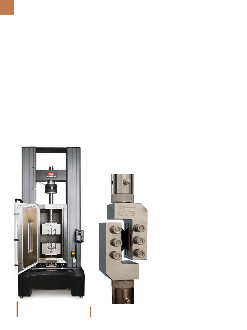
ASTM D7078 V-notched shear specimen
and test fixture.
Instron’s electromechanical machine is
capable of performing a variety of com-
posite tests over a range of temperatures.
results in a through-thickness tensile
stress in the curved section. On thicker
laminates it may be possible to perform
direct tension tests on cylindrical speci-
mens cut from the laminate.
In-plane composite compression
test methods provide a means of in-
troducing a compressive load into the
specimen and preventing buckling of
the specimen under the compressive
load. Three methods of introducing a
compressive load into a test specimen
include:
1. End loading: The load is introduced
by pushing on the flat end of the
specimen.
2. Shear loading: The load is intro-
duced into the wide faces of the
specimen.
3. Combined loading: A mix of shear
and end loading.
Two approaches are applied to
prevent buckling of test specimens,