


 20 / 62

A D V A N C E D M A T E R I A L S & P R O C E S S E S | F E B R U A R Y 2 0 1 6
2 0
FIELDASSISTEDSINTERING
TECHNOLOGYUPDATE—PART I
Field assisted sintering technology (FAST) enables cost-effective
manufacturing of metal, ceramic, and composite components
with sub-micron grain microstructures and tailored properties.
Jogender Singh, FASM, Penn State University, University Park, Pa.
Chris Haines, U.S. Army RDECOM-ARDEC, Picatinny Arsenal, N.J.
M
aking net-shape components
with sub-micron grain micro-
structures presents significant
challenges. Typical steps involved in
making these components using powder
materials include green compaction, sin-
tering at elevated temperatures, and hot
pressing to improve density. During these
conventional sintering and hot press-
ing processes, significant grain growth
occurs due to long thermal exposure,
thereby destroying the effective function-
ality of sub-micron grain materials in the
final component. Tomaintain sub-micron
grain microstructures in the compact-
ed and sintered product, sintering time
and temperature must be significantly
reduced. These challenges have been ad-
dressed with the introduction of field as-
sisted sintering technology (FAST). FAST
is known by different names as applied
by other laboratories, including plasma
assisted sintering (PAS), pulsed electric
current sintering (PECS), and electric
pulse assisted consolidation (EPAC). FAST
components are produced in a very short
time, i.e., a few minutes compared with
hours or days using conventional meth-
ods. Also, power consumption for FAST
is about 20% to 30% less than what is re-
quired by traditional techniques such as
pressureless sintering, hot pressing, and
hot isostatic pressing. FAST is ready to be
transferred toprivate industry for produc-
tion of net-shape components.
FIELD ASSISTED SINTERING
TECHNOLOGY
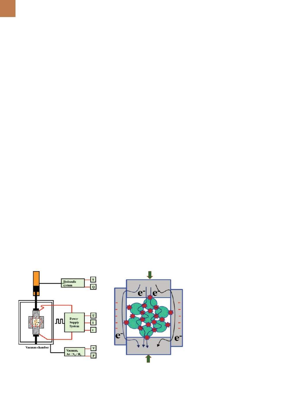
Figure 1 shows a schematic dia-
gram of a field assisted sintering sys-
tem. The powder material to be sintered
is contained in a graphite or metal die,
Fig. 1 —
(a) Schematic diagram of field assisted sintering technology/spark plasma sintering
technology and (b) materials interaction within mold.
and pressure is applied via an upper
and lower punch. Pulsed or continuous
mode dc current flowing through the
punch and die provides radiant heating
to the powder, while current flowing
through the powder produces instant
Joule heating. The combined effects
of pressure, temperature, high current
density, and localized heating at the
grain boundaries result in a high sinter-
ing rate. Sintering is carried out in a con-
trolled environment including vacuum,
backfilled argon, and nitrogen gas.
The Applied Research Laboratory
at Penn State is the only U.S. university
facility featuring three operational FAST
units (Fig. 2). These include an R&D unit
(FCT HP D 25) with a load capacity of
25 tons, an industrial prototype unit
(FCT HP D 250) with 250 ton capacity,
and a hybrid unit (FCT HB HPD 320) with
320 ton capacity. The hybrid unit
can manufacture components up to
350 mm in diameter and 100-150 mm
long. Units have a 2400°C maximum op-
erating temperature and provide up to
10,000 A of dc power. The system in-
cludes a digital radiation thermom-
eter (600°-3000°C range), specimen
displacement measuring equipment,
pressure control unit, and gas flow con-
troller. The mold assembly is placed in
a water-cooled vacuum system to elimi-
nate oxidation and contamination.
Technological benefits of FAST
compared with conventional process-
es include high flexibility; 100 to 1000
times faster processing cycle; retention
(a)
(b)