


 28 / 78

A D V A N C E D M A T E R I A L S & P R O C E S S E S | J A N U A R Y 2 0 1 6
2 8
toughness, and overall poor joint qual-
ity. Both optical and scanning electron
microscopy identified any intermetallic
compound present at the joint interface
as shown in Fig. 5.
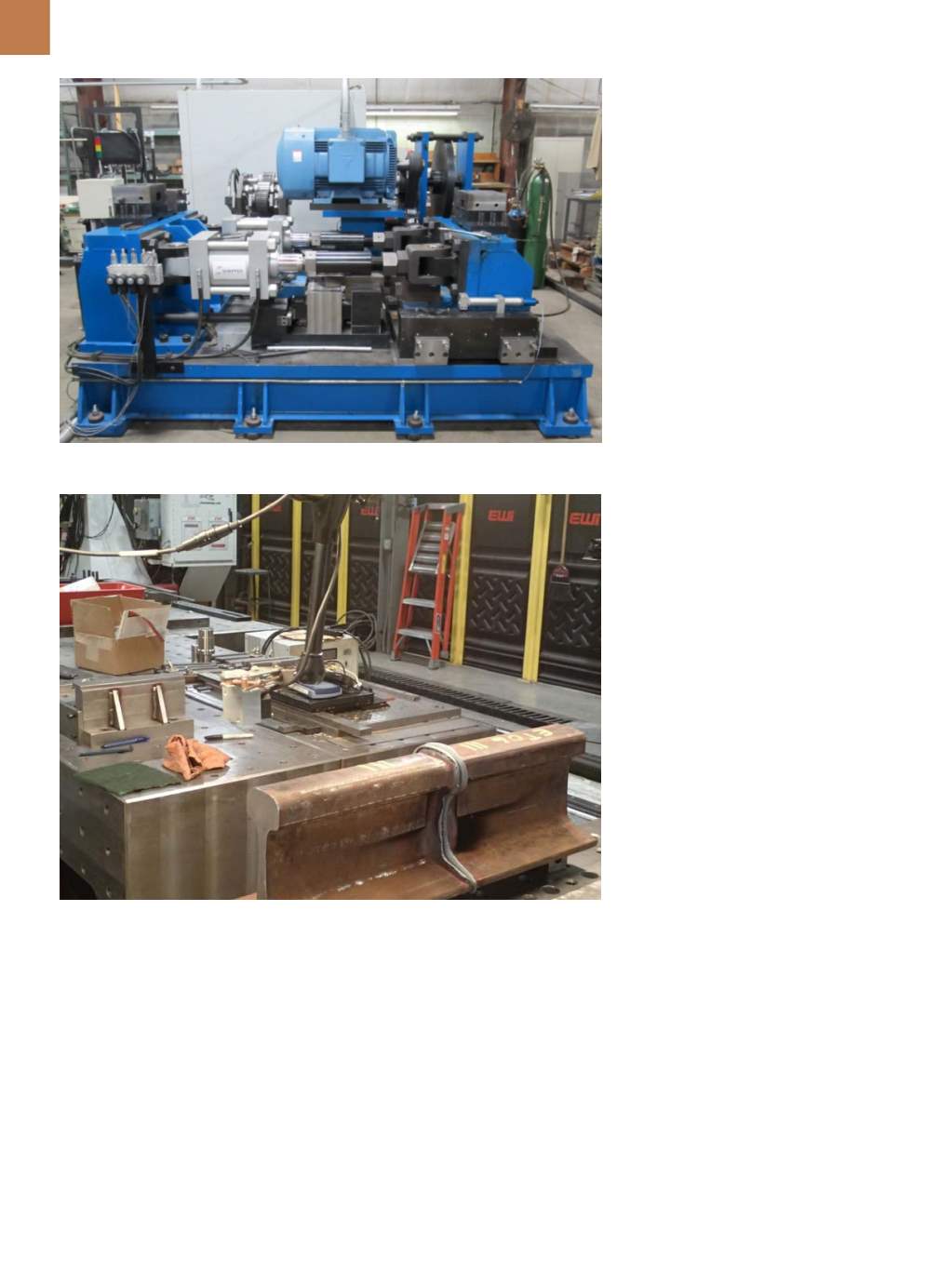
Working with the Federal Rail-
road Administration, EWI and APCI co-
developed a 150-ton mechanical LFW
machine (Fig. 6) capable of joining
full section railroad rail (8400 mm
2
)
[5]
.
This machine can apply up to 1335
kN of axial load and maintain part
Fig. 6 —
150-ton mechanical LFW system.
Fig. 7 —
Full-section rail joined by LFW.
oscillation under this load. Currently,
rail is joined using thermite or flash
butt welding, which results in exces-
sive rail shortening. LFW reduces rail
length loss from welding while main-
taining current joint performance.
This length loss reduction decreases
the tension placed on the rail due to
elongation. By reducing the stress
placed on the joint, rail service life is
greatly increased. A photo of a welded
rail is shown in Fig. 7.
SUMMARY
LFW is a solid-state process capa-
ble of joining noncircular parts by oscil-
lating one part under load to create fric-
tional heating. Advancements in LFW
machine design have led to a new me-
chanical oscillation system, enabling
new applications due to a decrease in
equipment cost, reduction of the ma-
chine footprint, and an increase in the
technology’s processing capabilities.
Potential applications vary from exist-
ing aerospace components and dissim-
ilar materials joining to heavy duty ap-
plications such as rail joining.
The LFW process is able to make
aluminum-to-steel joints with a match-
ing strength of aluminum alloy and also
produce full-section rail steel welds.
LFW is an emerging technology with
uses that are still being defined.
~AM&P
For more information:
Michael Eff is
a project development engineer, EWI,
1250 Arthur E. Adams Dr., Columbus,
OH 43221, 614.688.5212,
meff@ewi.org,
www.ewi.org.
References
1. S. Shapiro, Hydraulics at the Core
of the Largest Ever Welder,
Machine
Design,
machinedesign.com/article/ hydraulics-at-the-core-of-largest-ever- linear-friction-welding-machine-0316,2010.
2. I. Bhamji, et al., Solid State Joining
of Metals by Linear Friction Welding: A
Literature Review,
Materials Science &
Technology,
Vol. 27(1), p 2-12, 2011.
3. J. Gould and S. Johnson, Advances in
Translational Friction Welding through
Next Generation Mechanical Oscilla-
tors, TWI-EWI Aerospace Conference,
2012.
4. L. Ceschini, et al., A Study on Similar
and Dissimilar Linear Friction Welds of
2024 Al Alloy and 2124Al/SiCP Com-
posite, 6th International Conference
on Processing and Manufacturing of
Advanced Materials – THERMEC 2009,
p 461-466, 2010.
5. G. Jerry, W. Johnson, and S. John-
son, Application of Translational Fric-
tion Welding Rail Assembly and Repair,
AREMA 2012.