
A D V A N C E D
M A T E R I A L S
&
P R O C E S S E S | J A N U A R Y
2 0 1 6
3 1
strength and joint quality evaluations
closer to the core central axis. The wire,
including the joint area, was ground to
diameters of 0.014, 0.010, and 0.008 in.,
then tensile tested to evaluate change
in joint strength throughout the cross-
sectional area. After initial joint strength
and quality assessments, full guidewires
were assembled using cores joined with
the LRM solid-state weld process from
0.014-in. stainless steel and 0.014-in.
Nitinol. The core wire distal grind pro-
file for this study mimicked the stiffness
profile of a commercially available bi-
metal guidewire, enabling performance
comparisons between the two designs.
The competing design wire consisted of
Nitinol and stainless steel joined via a
Nitinol hypotube and adhesive. The two
designs were tested side-by-side com-
paring lateral stiffness, tensile strength,
and simulated clinical performance in
a 2D plate model emulating a tortuous
vessel. After tensile testing, the fracture
surface was analyzed using a tabletop
SEM (Hitachi TM 300).
EXPERIMENTAL RESULTS
Results show that the new solid-
state welding process produces a clean
and defined transition between the
stainless steel and Nitinol and that the
interface is free of defects and/or po-
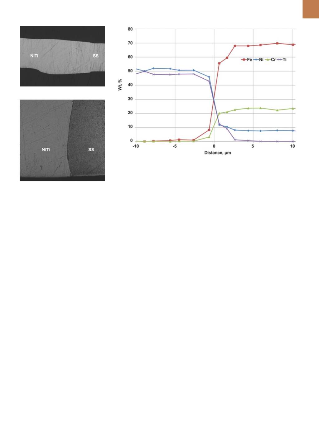
rosity. Figure 1 shows SEM images of a
joint cross-section between 0.018-in.
stainless steel and 0.020-in. Nitinol.
Figure 1(a) shows the interface after
polishing while Fig. 1(b) shows the in-
terface after etching the stainless steel
side. The heat-affected zone (HAZ) is
approximately 0.012-in. (~300 µm) long,
and is distinguished from the drawn
wire elongated grain structure by the
presence of a fine, uniform grain struc-
ture. A fine grain size is an inherent
solid-state processing advantage com-
pared to fusion welding, which is char-
acterized by the presence of a cast den-
dritic structure and large grains in the
HAZ
[2,7]
. Figure 2 shows the EDS analysis
at the interface of the solid-state weld
joint, collected within 10 µm on either
side of the joint. The data shows that
chemical intermixing of Nitinol and
stainless steel extends approximately
1 µmon either side of the joint interface.
LRM engineers ground welded
0.018-in. stainless steel and 0.020-in.
Nitinol wires to different diameters,
post joining in order to determine joint
grindability, thus providing design
options and an assessment of joint
strength uniformity toward the wire
central axis. All tested samples passed
the U-bend preconditioning test, which
indicates excellent joint bending prop-
erties. Tensile tests yielded an average
joint strength of approximately 80% of
the tensile strength of Nitinol wire. All
tensile samples failed at the stainless
steel to Nitinol interface, leading to
the hypothesis that a relatively small
HAZ and presence of fine grain struc-
ture contribute to the high strength of
the joint. With small sample sizes, 95%
of the confidence interval indicates no
loss of stiffness as the core diameter is
reduced via grinding as seen in Fig. 3.
Full guidewires were built using
the proprietary solid-state welded
joints located approximately 40 cm
from the distal tip. The grind profile
and joint location aligned with leading
competitive guidewires and enabled
comparative bench testing. Figure 4
shows the lateral stiffness results,
and the inset of Fig. 4 shows the LRM
solid-state weld joint in comparison
to the hypotube joint design. It is evi-
dent that the LRM joint is significantly
shorter than the 3-cm long hypotube
joint. The solid-state weld also shows
a smooth and even bending transition
from stainless steel to Nitinol, while the
Fig. 1 —
Post polishing SEM image of joint
shows its seamless nature (a); SEM image of
joint after etching shows presence of small
grains in HAZ (b).
(a)
(b)
Fig. 2 —
EDS composition profile at the interface for LRM solid-state weld joint.


