


 26 / 78

A D V A N C E D M A T E R I A L S & P R O C E S S E S | J A N U A R Y 2 0 1 6
2 6
L
inear friction welding (LFW) is a
solid-state process that uses friction
and plastic deformation to gener-
ate heat. A metallurgical bond between
two pieces of material is achieved via
relative motion (i.e., friction) of mate-
rials under applied force. Solid-state
welding processes join without melting
materials and are in high demand due to
their superior weld quality, ability to join
non-fusion-weldablematerials, and over-
all lower peak temperatures than fusion
welding processes.
LFW is closely related to rotary fric-
tion welding, which uses relative angu-
lar motion under force to generate heat.
However, LFW uses
translational
motion
rather than
rotational
motion and is thus
able to join noncircular cross-sections as
well. Despite its advantages, industrial
applications of LFWhave been limited to
high value-added components such as
jet engine components due to prohibi-
tive equipment costs.
Recently, new advancements in os-
cillator technology have reduced equip-
ment costs and expanded LFW’s com-
mercial viability into applications ranging
from producing aluminum-to-steel joints
to the joining of railroad rails.
OSCILLATOR TECHNOLOGY
ADVANCEMENTS
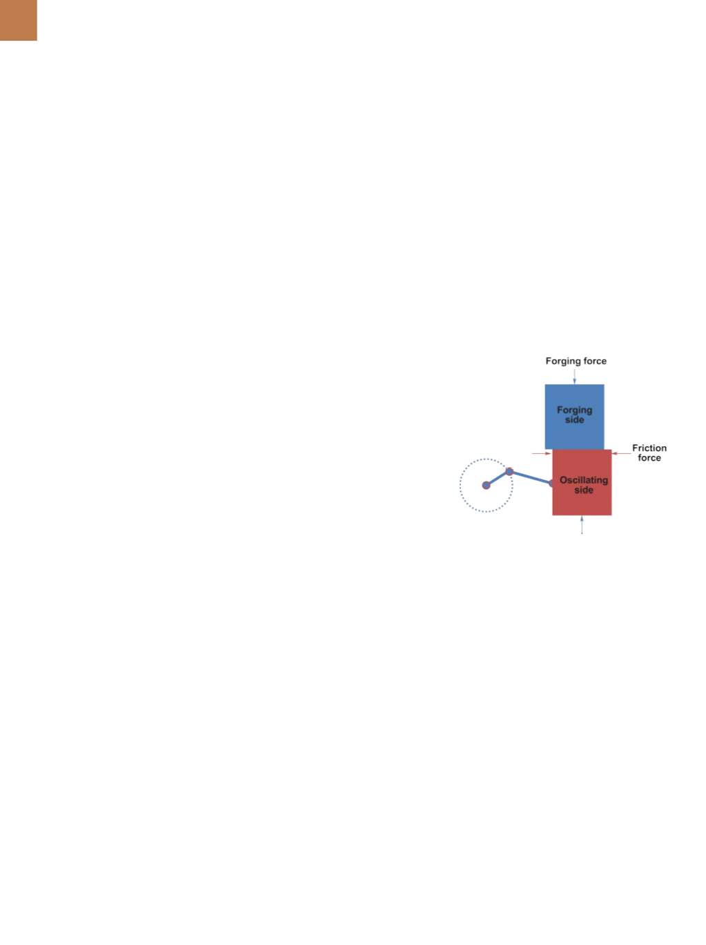
LFW achieves friction heating and
plastic deformation at the interface be-
tween the two components tobe joined.
As the material is heating, it is extruded
away from the joint and a new surface,
called a
nascent surface,
is formed. By
stopping oscillation and forging once
the nascent surface is formed, a weld is
made between the two pieces. A sche-
matic of this process is shown in Fig. 1.
Key variables for LFW include the
axial load along with oscillation fre-
quency, amplitude, and duration. LFW
machines must achieve the desired
relative velocities between two parts,
apply axial loads, and precisely stop
oscillation to align parts after weld-
ing. In order to maintain high relative
velocities under an axial load, shear
loads during welding can become
large. Therefore, designing an oscilla-
tor that can withstand the shear loads
opposing oscillation is one of the most
critical—and costly—factors of an LFW
machine.
Current LFW systems are most-
ly hydraulic actuation systems, which
store energy under high fluid pressure
that is first directed to one side of a
drive cylinder and then to the other
side to generate oscillation. High speed
valves with large flow rates, many paral-
lel circuits, and hydraulic accumulators
are required for hydraulic control and
must change flow direction in 1/60th
of a second to achieve a 60-Hz oscilla-
tion. Hydraulic servo valves operating
at speeds up to four times faster than
typical industrial servo valves provide
amplitude control
[1]
.
These machines require a signif-
icant investment in both capital and
floor space and are also complex to
operate and maintain. Due to their
size and complexity, hydraulic LFW
machines have been relegated to pro-
ducing only the highest value parts
for the most demanding applications.
A primary application for these sys-
tems is welding blades to disks for jet
engines
[2]
.
One
specialized
equipment
builder, APCI LLC, South Bend, Ind.,
recently developed a unique me-
chanically based oscillator for LFW.
Instead of the complex hydraulic sys-
tems used to oscillate a part, a motor
drive with a continuously variable
stroke crank
[3]
performs this task. Mo-
tor rotation drives the crank, which
translates rotary motion into linear
LINEAR FRICTIONWELDING
UPDATE: LOWERCOSTS,
BROADERAPPLICATIONS
From joining railroad rails to producing strong aluminum-to-steel
joints, recent advancements in linear friction welding are
reducing equipment costs and expanding potential uses.
Michael Eff, Jerry Gould, and Tim Stotler
EWI, Columbus, Ohio
Fig. 1 —
Mechanical LFW schematic.