


 25 / 102

A D V A N C E D
M A T E R I A L S
&
P R O C E S S E S |
O C T O B E R
2 0 1 5
2 5
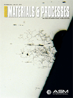
Fig. 8 —
Predictedmaximumprincipal stress
for welding with flux-cored arc welding.
Fig. 9 —
Predictedmaximumprincipal
stress for welding with electron beam
welding.
the weld (N117) and the base metal
(MO-RE1). This stress distribution could
explain the crack type A observed in the
weld macrograph, as shown in Fig. 3.
Electron beam welding (EBW)
without filler metal could eliminate the
high stress near the weld (Fig. 8). Anoth-
er FEA was conducted by replacing the
material properties in the weld using
base material properties and keeping
other conditions the same. Figure 9
shows the predicted maximum princi-
pal stress with EBW without using filler
metal. High stress near the weld dis-
appears, as shown in Fig. 9. Therefore,
EBW is an effective method to improve
the creep-fatigue life of the furnace roll
in the hot-dip coating line. A prelimi-
nary welding test shows that EBW could
be used to weld the furnace roll.
SUMMARY
A longstanding problem with hot-
dip coating lines is that the furnace roll
often fails in less than one year. By exam-
ining the service history of a failed roll, it
was discovered that the furnace roll was
working under conditions involving both
thermal and mechanical cyclic load-
ing, in addition to high temperatures.
Therefore, creep-fatigue damage could
occur during roll service. Macroscopic
examination of the welded joint found
two kinds of cracks—crack A at the weld
root and crack B at the weld toe. Crack
type A initiated from the weld root and
www.masterbond.com Hackensack, NJ 07601 USA +1.201.343.8983 • main@masterbond.com Beat the clock f r o m 4 K t o 4 0 0 ° F 5 – 1 0 m i n u t e s a t 3 0 0 ° F r ig o r o u s t h e r m a l c y c l i n g S e r v i c e a b l e R a p i d c u r i n g : W i t h s t a n d s > 3 2 0 0 p s i 2 0 – 2 5 p l i T e n s i l e l a p s h e a r s t r e n g t h T - p e e l s t r e n g t h with F A S T C U R I N G S T R U C T U R A L A D H E S I V E S U P R E M E 1 0 H T F 11063LK_3.25x4.875_Supreme10HTF-1.indd 1
8/26/15 4:25 PM
propagated to the outer surface of the
weld, which resulted in separation be-
tween the roll shell and end bell. Defects
such as inclusions and incomplete joint
penetration were also found.
A new furnace roll design was pro-
posed to avoid the through-weld crack
in which the weld was rotated by 90
°
. In
addition, the roll material was replaced
with MO-RE1. Finite element analysis
was used to evaluate
the new design. Re-
sults show that high
stress occurs in the
interface between the
weld and base metal,
which is induced by
the difference between
the thermal expansion
coefficient of the weld
and base metal. Elec-
tron beam welding
without filler metal
can eliminate the high
stress near the weld.
Therefore, the new
design, in conjunction
with the new welding
process, could solve
the historical roll fail-
ure problem.
~AM&P
For more information:
Yu-Ping Yang is princi-
pal engineer, model-
ing group, EWI, 1250
Arthur E. Adams Dr.,
Columbus, OH 43221,
614.688.5253,
yyang@ ewi.org,
www.ewi.org.References
1. G.H. Awan, TheMorphology of Coating-
Substrate Interface inHop-Dip-Aluminized
Steels, University of Engineering and
Technology, Pakistan, Ph.D. dissertation,
2001.
2. C.M. Cotell, J.A. Sprague, and F.A.
Smidt,
ASM Handbook,
Volume 5:
Surface Engineering,
p 339-348, 2007.
3. M.B. Isiko, Aluminizing of Plain
Carbon Steel—Effect of Temperature
on Coating and Alloy Phase
Morphology at Constant Holding
Time, Norwegian University of Science
and Technology, TMT4905 - Materials
Technology, Masters thesis, 2012.