


 24 / 102

A D V A N C E D M A T E R I A L S & P R O C E S S E S | O C T O B E R 2 0 1 5
2 4
These temperature variations resulted
in cyclic thermal loading on the roll.
In addition, the mechanical load used
to transport the strip was applied on a
90
°
section of the roll. Because the roll
was rotating continuously, it was also
subjected to a cyclic mechanical load.
Therefore, the furnace roll was working
under conditions involving both ther-
mal and mechanical cyclic loading, in
addition to high temperature. These
conditions could lead to creep-fatigue
damage during service.
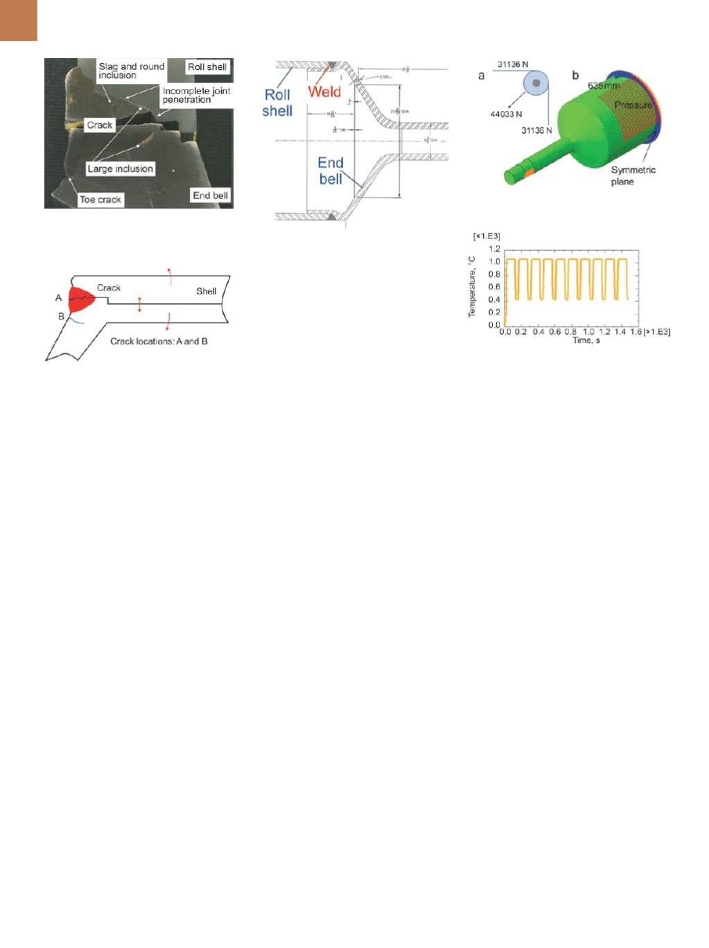
Macroscopic examination of the
welded joint identifies why failure oc-
curred. Figure 3 shows a macrograph of
the weld cross-section prepared by cut-
ting the failed roll. Two kinds of cracks
(Fig. 4, A, B) were found near the weld.
Crack type A initiated fromtheweld root
and propagated to the weld’s outer sur-
face, resulting in a separation between
the roll shell and end bell. Crack type B
appears near the weld toe, which may
be the result of stress concentration
due to geometric discontinuities during
cyclic loading. In addition, defects such
as inclusions and incomplete joint pen-
etration were found in the weld. Al-
though the inclusion did not contribute
to roll failure, the incomplete joint pen-
etration may have triggered the failure
if combined with tensile stress.
FURNACE ROLL REDESIGN
As shown in Fig. 4, the weld root
in the furnace roll’s current design is
a potential crack location due to the
mechanical load from transporting the
steel strip. To avoid the through-weld
crack (crack type A in Fig. 4), the weld
that joins the end bell to the roll shell
was redesigned, as shown in Fig. 5. In
the new design, the weld is rotated 90
°
and moved slightly away from the end
bell to the shell shoulder, which may
further reduce weld stress. Further, the
material (high-temperature alloy 22-H)
used to make the end bell and roll shell
is replaced with MO-RE1.
NEW DESIGN EVALUATION
Finite element analysis (FEA) was
used to evaluate the new furnace roll de-
sign. Due to the symmetry of geometry
and loads, a half FEA model was used in
the analysis. Symmetric boundary con-
ditions were applied in the symmetric
plane, as shown in Fig. 6b. Temperature-
dependent material properties were in-
put to the FEA model for base material
MO-RE1 and filler material N117.
Steel sheet tension of 31,136 N is
transferred to the roll through contact
on 25% of the roll circumference over a
width of 1270 mm in the center of the
roll length and reacted on the journals,
as shown in Fig. 6a. In the FEA model,
forces were combined and converted
into a pressure applied in the 45
°
di-
rection, as shown in Fig. 6b. Finite ele-
ment grids show the pressure applied
surface, which is a 90
°
section in the
designed roll. Gravitational force is also
included in the model. Pressure and
gravity were balanced by supporting
the journal from each end of the roll.
Heat transfer analysis was used
to predict the temperature history of
the welded roll by modeling heat con-
vection from hot air inside the furnace
using Abaqus software and a user-
developed subroutine. The heat flux
(
q
) was calculated using equation (1) in
which the heat convection coefficient
(
h
) was input as a constant number,
20 W/m
2
C.
T
s
represents furnace tem-
perature, which varies by location and
time. Figure 7 is the predicted tempera-
ture on the roll for 10 heating cycles.
q
= h(T – T s )
(1)
Transient, static, stress, and dis-
placement analyses with time-depen-
dent material responses were con-
ducted using the Abaqus commercial
finite element code and inputting the
predicted temperature history. Isotropic
creep and plasticity coupled behavior
was modeled by solving a coupled sys-
tem of constitutive equations. Figure 8
shows the predicted maximum principal
stress after the 10th cycle (Fig. 7). Stress
magnitudes are lowbecause the roll is at
a relatively high temperature of 427
°
C.
High stress is observed in the interface
between theweld and basemetal, which
could be induced by the difference of
thermal expansion coefficient between
Fig. 3 —
Defects and cracks near the welded
joint.
Fig. 4 —
Current furnace roll design.
Fig. 5 —
New furnace roll design.
Fig. 6 —
Mechanical load applied on the roll.
Fig. 7 —
Thermal load applied on the roll.