



 19 / 54

technologies enable construction of complex features,
hollow cooling passages, and high precision parts, they
are limited by the build envelope, single material per
build, and horizontal layer construction ability. In com-
parison, directed energy deposition technologies offer
larger build envelopes and higher deposition rates, but
their ability to construct hollow cooling passages and
finer geometry is limited. Direct metal deposition (DMD)
and laser engineered net shaping (LENS) technology can
deposit multiple materials in a single build and add metal
to existing parts.
Commercially available AM technologies melt pow-
der or wire feedstock using either laser or electron beam
heat sources. Laser-based systems operate under inert
atmosphere (for titanium processing) in contrast to the
vacuum environment of electron beam systems. While
vacuum systems are more expensive, they offer low
residual stress compared to laser-based systems, and
electron-beam-processed parts can be used without
stress relieving operations. Heat source effects on me-
chanical properties are discussed in more detail further
in this article.
Powder bed fusion
Powder bed fusion technologies place a layer of metal
powder on the build platform and then the powder is
scanned with a heat source, such as a laser or electron
beam, to either partially or completely melt the powder in
the path of the beam and resolidify and bind it together as
it cools (ASTM specification F2924-12a and -13 for Ti-6Al-
4V and Ti-6Al-4V ELI grades, respectively). Layer-by-layer
tool path tracing is governed by the CAD data of the part
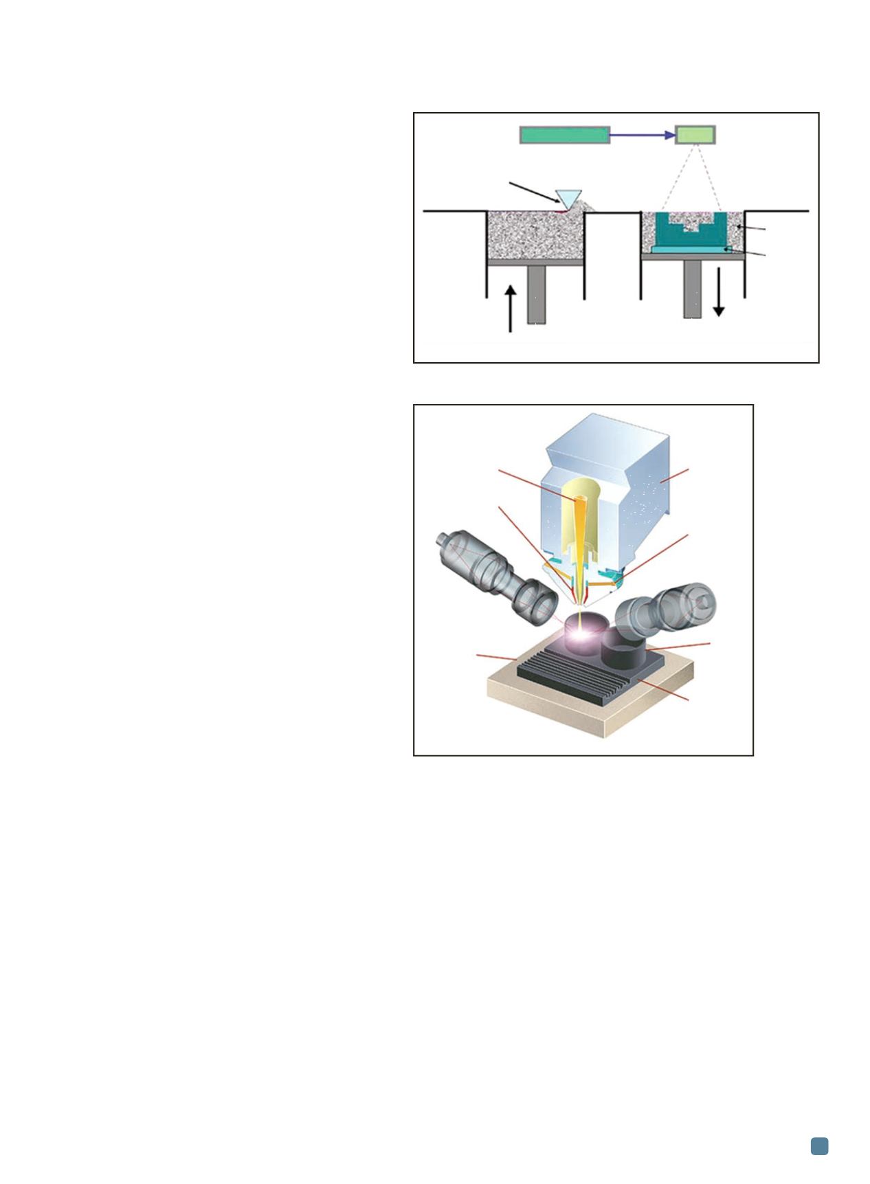
being built. Figure 1 shows a schematic explaining the steps
involved in this process:
• A substrate is fixed on the build platform.
• The build chamber is filled with inert gas (for laser
processing) or evacuated (for electron beam
processing) to reduce the chamber’s oxygen level to
the desired level.
• A thin layer of metal powder (20-200 mm thick,
depending on the technology and equipment) is
placed on the substrate and leveled to a
predetermined thickness.
• The laser or electron beam scans the powder bed
surface following the tool path precalculated from the
CAD data of the component being built.
• This process is repeated for the following layers until
the build is complete.
Directed energy deposition
Directed energy deposition technologies work by in-
jecting material into a meltpool rather than scanning a
powder bed (AMS specification 4999A for Ti-6Al-4V). Fig-
ure 2 shows a schematic of DMD technology (laser-based
metal deposition). Steps for the directed energy deposition
process include:
• A substrate or existing part is placed on the work
table.
• Similar to powder bed fusion, the machine chamber
is closed and filled with inert gas (for laser
processing) or evacuated (for electron beam
processing) to reduce the chamber’s oxygen level to
the desired level (AMS 4999A specifies below
1200 ppm). The DMD process offers local shielding
and does not require an inert gas chamber for less
reactive metals than titanium, such as steels, Ni
alloys, and Co alloys.
• At the start of the cycle, the process nozzle with a
concentric laser or electron beam is focused on the
part surface to create a meltpool. Material delivery
involves powder traveling through a coaxial nozzle
(laser) or through a metal wire with a side delivery
(electron beam). The nozzle moves at constant speed
and follows a predetermined toolpath created from
the CAD data. As the nozzle (tooltip) moves away,
the meltpool solidifies and forms a metal layer.
ADVANCED MATERIALS & PROCESSES •
FEBRUARY 2014
19
Fig. 1 —
Schematic showing powder bed fusion technology.
Courtesy of Jim Sears.
Fig. 2 —
Schematic showing direct metal deposition
technology. Courtesy of DM3D Technology.
Laser system
Scanner system
Powder coater
Loose
powder
Build
plate
Build station
Powder delivery piston
system
Laser beam
Nozzle
shielding gas
Feedback
sensor 1
Workholding
fixture
Final focus
optics
To powder
feeder
Feedback sensor 2
Solid freeform
shape
by direct
deposition
Substrate or die
preform