



 16 / 54

Extrusion Welding
in a Magnesium Alloy
(AM30) Hollow Section Extrudate
T
he number of magnesium extruded
parts used in the automotive industry is
increasing due to their lightweight and
high specific mechanical properties that facili-
tate reduced fuel consumption. However, tech-
nical challenges in the deformation processing
of magnesium alloys exist and include low
formability, which is attributed to their hexag-
onal close packed (hcp) crystal structure. The
extrusion process is a promising metal forming
process because it applies the hydrostatic com-
pression state of stress in the deformation zone,
enabling improved workability.
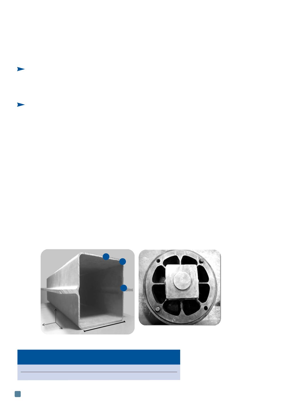
Producing hollow section profiles, such as
the double hat extrudate shown in Fig. 1, uses a
porthole die as shown in Fig. 2. When a magne-
sium alloy billet is extruded through the port-
hole die, material is separated by eight die arms
into strands, which are then joined together
under high temperature and high pressure con-
ditions in the die’s welding chamber. This join-
ing process occurs as solid-state bonding and is
known as extrusion welding. The main objec-
tive of this work is to better understand the in-
tegrity and microstructure of extrusion welding
in a magnesium alloy (AM30) hollow section
extrudate (See Table 1).
Metallographic sample preparation
Preparing metallographic samples of mag-
nesium alloys is challenging because the alloys
are relatively soft and can be easily scratched
during preparation. In addition, twin deforma-
tion can occur during polishing and will be vis-
ible after etching. Further, some intermetallic
particles always contaminate the polishing
cloths and can cause additional scratches.
Water should be avoided during the final pol-
ishing process because magnesium alloys have
a tendency to stain when exposed to water-
based liquids.
Due to the extrusion profile symmetry, only
three locations (A, B, and C) are shown in Fig.
1, which are equivalent to all eight extrusion
welds that were metallographically investi-
gated. Specimens were sectioned transversely
to the extrusion direction, mounted, ground,
and polished using standard metallographic
specimen preparation techniques. Specimens
were then chemically polished using 100 mL
methanol, 12 mL hydrochloric acid, and 8 mL
nitric acid for 10 seconds. Finally, specimens
were etched using a solution of acetic picral (4
g picric acid, 5 mL acetic acid, 10 mL H
2
O, 100
mL ethanol) for 5 seconds
[1]
.
Results
Figures 3, 5, and 6 are each a collage of po-
larized light optical microscopy (LOM) images
in locations A, B, and C, respectively, and show
the different types of extru-
sion welding.
Figure 3 shows the differ-
ence in grain sizes between
the middle of the image
where the extrusion welding
occurred and the rest of the
extrudate near the edge of
the image represents a less-
modified alloy microstruc-
ture in the welding chamber.
Figure 4 is a magnified
image captured in the mid-
dle of the specimen in loca-
tion A (see Fig. 3), which
shows good extrusion weld integrity with no vis-
ible weld line. On the other hand, Figs. 5 and 6
show different types of extrusion welding with a
curved weld line. The presence of the line is
most likely due to oxidization of the strands’ sur-
faces or insufficient pressure and/or tempera-
ture. These welding lines could be straight or
tortuous, depending on the velocities of the two
Nabeel H. Alharthi*
Lehigh University
Bethlehem, Pa.
King Saud University
Riyadh, Saudi Arabia
Wojciech Z.
Misiolek, FASM*
Lehigh University
Bethlehem, Pa.
ADVANCED MATERIALS & PROCESSES •
FEBRUARY 2014
16
*Member of
ASM International
JACQUET-LUCAS AWARD
This entry won
the prestigious
Jacquet-Lucas
Award for
Best in Show
at the 2013
International
Metallographic
Contest held in
conjunction
with the
M&M 2013
conference in
Indianapolis.
TABLE 1 — NOMINAL CHEMICAL COMPOSITION
OF ALLOY AM30 (wt%)
Mg
Al
Mn
Zn
Fe
Ni
Cu
Balance 3.4
0.33
0.16 0.0026 0.0006 0.0008
Fig. 1 —
Investigated extrusion welding locations
of the AM30 profile.
Fig. 2 —
Porthole die
used for the double
hat extrusion.
A
B
C
ND
TD
ED
102 mm