


 23 / 50

ADVANCED MATERIALS & PROCESSES •
JANUARY 2014
23
materials are being developed for materials subjected to
sliding and galling wear conditions
[6]
.
Advanced methods of materials characterization are
needed, in part, because examined materials may exhibit
either a combination—or all—of the following phases: Fer-
rite, austenite, martensite, carbides, and nitrides. Addition-
ally, and under the immense local deformation process that
occurs during galling or sliding wear, examined materials
may exhibit a combination of phase transformations (ei-
ther by stress or rapid temperature rise at the surface), pref-
erential deformation of phases, strain localization, and/or
oxidation. All of these factors may contribute to overall ma-
terial performance. Furthermore, resistance to wear is tem-
perature dependent, making it imperative that materials be
examined across the entire range of potential valve operat-
ing conditions.
Hardfacing alloy performance is determined in part by
the transition of the wear mechanism during in-
creasing load. Metal alloys in unlubricated slid-
ing contact typically undergo adhesive wear with
micron-sized particle formation at low to inter-
mediate loads. Above a critical load, however,
many metals exhibit a transition to galling, with
large surface deformations and bonding, accom-
panied by significant wear debris, high friction,
and eventual seizure. In austenitic hardfacing
materials, such as Alloy 6, resistance to galling
and sliding wear is a result of a strain-induced
martensite phase transformation, which is a con-
sequence of high work hardening at the contact
surfaces. In martensitic hardfacing materials,
such as Everit 50, the transition to galling can be
eliminated as a result of a deformable tribofilm
formation due to phase transformations to
austenite (i.e., a micron-dimension sacrificial
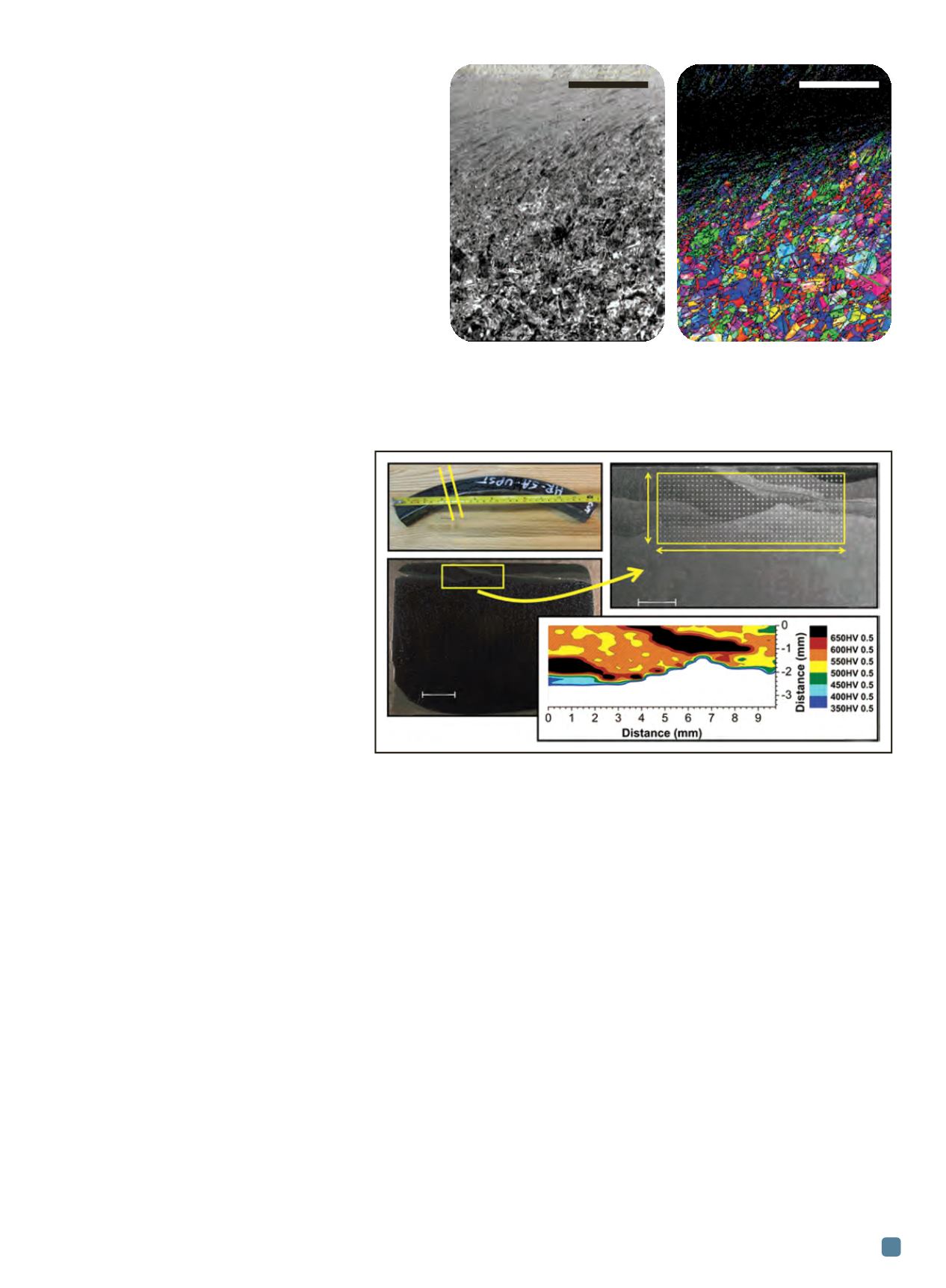
layer). An example of results provided using
SEM-EBSD for a button tested to ASTM G98 is
shown in Fig. 3. Understanding these fundamen-
tal wear mechanisms is vital to the design and optimization
of hardfacing materials candidates.
Solutions depend on collaboration
Serious deficiencies exist regarding compatibility of
given substrate materials, the butter layer (also known as
buffer layer), and the selected hardfacing material for use in
cycling fossil applications. Performance inconsistencies, in-
cluding failure time and crack location, can be partially at-
tributed to the many material combinations already
identified, such as: Grade 22 and 91 substrates; 309 stain-
less steel, Alloy 625 and Alloy 21 butter layers, and Alloy 6
or 21 hardfacing layers. Recent investigations into the fail-
ure mode reveal at least two contributing components to
the rash of documented failures—a brittle, hard metallur-
gical phase with little inherent ductility and accumulation
of welding residual stresses, which may assist or drive crack
initiation and/or propagation in service. Cracking in serv-
ice follows the hard region highlighted in black (>650 HV
0.5) shown in Fig. 4. Work is currently underway to take
advantage of inherent advantages in the PM/HIP process—
such as low dilution and no issues regarding weldability—
to address and solve issues associated with delamination
of hardfacing materials.
To solve some of the industry’s most challenging con-
cerns, collaboration among end users, manufacturers, and
research organizations must occur. By integrating the ef-
forts of various industry players in mutual research and de-
velopment, a wide range of research tools, fundamental
disciplines, and engineering expertise can help achieve
faster and better technology advances. This approach typ-
ically results in sound engineering solutions that are more
likely to be implemented in the long-term. This is because
research results are critically reviewed and, in many cases,
an eventual consensus may be reached regarding the best
path forward. With this in mind, several key items have
been achieved in this project so far, including:
• Identification of wear mechanisms in candidate
austenitic materials and martensitic materials for
nuclear valve applications.
Fig. 3 —
Scanning electron microscope image (left) and electron back
scatter diffraction (EBSD) image (right) of a cross-section from an ASTM
G98 button specimen. The massive deformation near the specimen surface
is indicated by a large black region in the EBSD image. Image analysis was
conducted through a collaborative effort between The Ohio State University
and the BAM Institute.
Fig. 4 —
Results of a hardness map (c and d) conducted on a cross-section (b) taken
from an out-of-service hot reheat valve seat (a). The hardness values exceed 650 HV 0.5,
a significant level as Alloy 6 normally exhibits an as-deposited hardness value of roughly
450 HV 0.5.
(a)
(c)
(b)
(d)
Removed sample
3.5 mm
10.0 mm
573 indents, 500 g load,
0.25 mm spacing
5 mm
2 mm
200
m
m
200
m
m