
sion reactions in the Zr alloy is an
important cladding degradation
mechanism
[2]
. The hydrogen can
form a zirconium-hydride phase in a
plate-like morphology with associ-
ated embrittling effects in the
cladding. The orientation of these
hydride phases (circumferential or
radial, Fig. 1) continues to be the
subject of ongoing studies. Delayed
hydride cracking (DHC) is a particu-
lar concern when hydrides dissolve
and reprecipitate in an orientation
more favorable to crack initiation.
Other components of LWR such
as steam generator tubing, pipes, con-
trol rod drive mechanisms, core sup-
port structures, and shroud bolts are
made with materials such as AISI 304
and 316 stainless steels, and Ni-based
alloys such as Alloys 600, 690, 718,
and 800H. SCC is a concern in these
components, particularly at welds.
For 304 and 316 stainless steels, sensi-
tization dramatically promotes SCC.
Very low carbon nuclear grade (NG)
stainless steels and stainless steels
with niobium additions (grade 347)
with superior resistance to SCC have
been developed. Hydrogen is often in-
jected into the water in BWR to
negate the effect of dissolved oxygen
and reduce SCC. Alloy 600 was em-
ployed for steam generator piping,
but intergranular cracks were ob-
served after multiple years of service.
Alloy 690 with higher resistance to
SCC is being considered.
Lead fast reactors
Lead fast reactors (LFR) provide
notable benefits such as burning long-
lived actinides to shorter-lived ones,
and alleviate the challenge of long-
term nuclear waste storage. LFRs typ-
ically use a liquid Pb-Bi eutectic (LBE)
alloy as coolant. LBE has a low neu-
tron cross section, low melting point
(~123.5°C), and excellent thermal
properties. Operating temperatures
are in the 350-550°C range. Corrosion
resistance of structural materials in
contact with high temperature liquid
LBE is an important requirement in
this type of reactor. Primary corrosion
mechanisms are long-term dissolu-
tion of the alloy in liquid LBE and ox-
idation of the alloy surface from
reaction with oxygen in the LBE melt.
Ni, Fe, and Cr have solubility in LBE,
but Ni has particularly high solubility.
For this reason, Ni-based alloys may
not be suitable for this application.
Ferritic steels are being actively
considered for LBE environments. It is
desirable to have a small amount of dis-
solved oxygen in the LBEmelt to enable
a thin “self-healing” protective oxide
layer to formon the surface as a barrier
between LBE and the underlying steel.
Free energy considerations favor the
formation of Fe-, Cr-oxides relative to
PbO and BiO. Higher oxygen concen-
trations, however, can lead to thicker
andmechanically unstable oxides mak-
ing active oxygen control in the LBE
melt crucial. A typical oxygen concen-
tration window is deemed to be in the
range of 1 × 10
-6
to 1 x 10
-8
wt% de-
pending on the steel and temperature
[4]
.
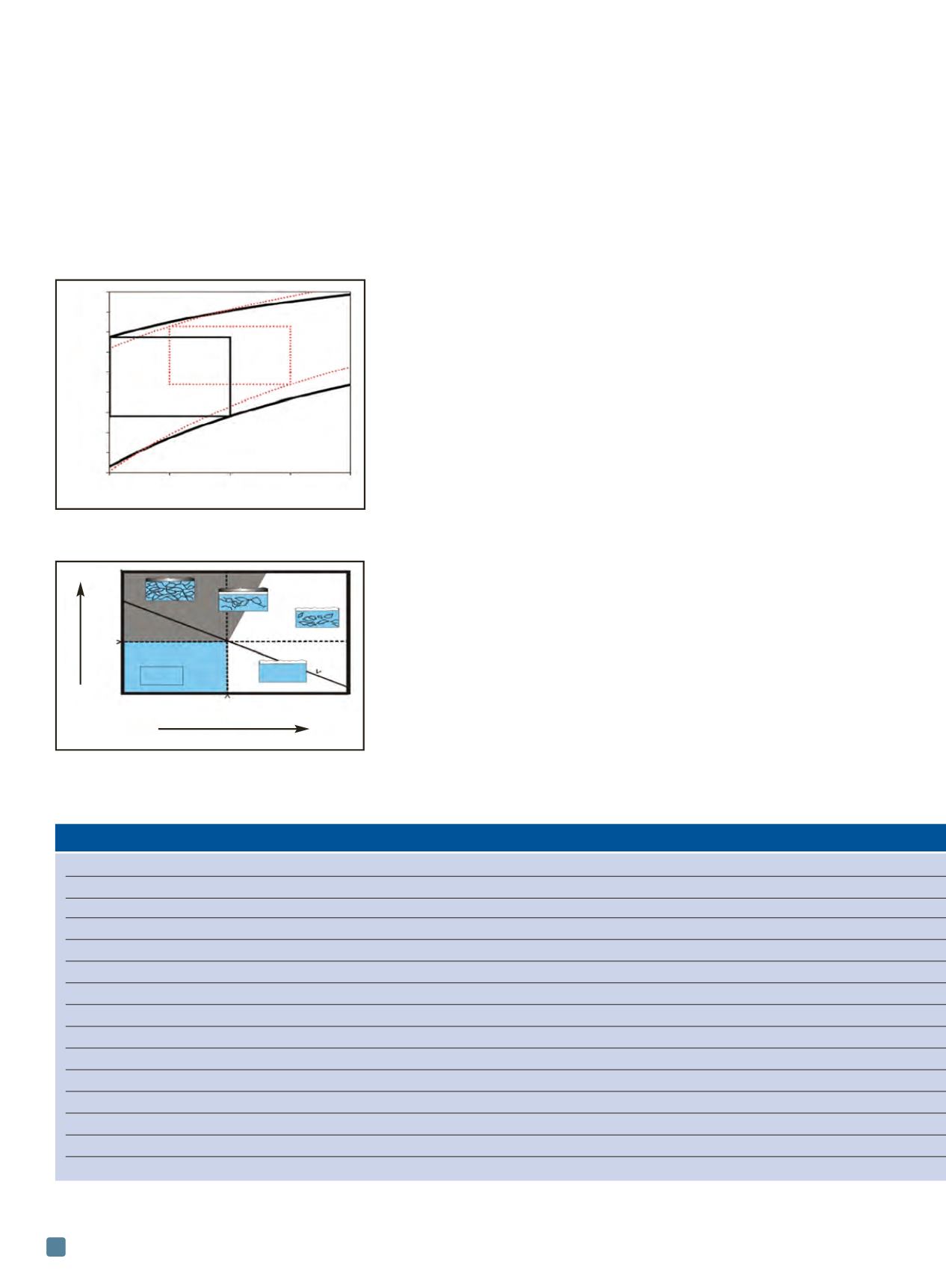
Figure 2 shows the oxygen concentra-
tion and coolant temperature regime
ADVANCED MATERIALS & PROCESSES •
JANUARY 2014
18
TABLE 1 — ALLOY COMPOSITION
Concentration, wt%
[4]
Material
Fe
C
Mn
Si
Cr
Ni
Mo
Al
V
W
HT-9
Bal.
0.18
0.4
0.2
12.26
0.49
1
— 0.3
0.46
T91
Bal.
0.105
— 0.43
8.26
0.13
0.95
— 0.2
—
EP823
Bal.
0.16
0.55
1.09
11.7
0.66
0.74
— 0.3
0.6
MA756
Bal.
0.04
— — 20
— — 4.5
— —
PM2000
Bal.
0.01
— — 20
— — 5.5
— —
316L
Bal.
0.002
1.8
0.46
17.5
12.3
2.3
— — —
Alloy 600
6.0-10 <0.15 <1.00 <0.50 14-17 Bal.**
— — — —
Alloy 690
7.0-11 <0.05 <0.50 <0.50 27-31
Bal.
— — — —
IN718
Bal.
<0.08 <0.35 <0.35 17-21 50-55** 2.8-3.3 0.2-0.8
— —
304 SS
Bal.
<0.08 <2.0
<1.0 17.5-20 8.0-11
— — — —
347 SS
Bal.
<0.08 <2.0
<1.00 18.0
11.00
— — — —
IN 800H
Bal.
0.05-0.1 — — 19-23 30-35
— 0.15-0.6 — —
Hastelloy-N 4.0-6.0 0.04-0.08 — — 6.0-8.0 Bal.
15-17
— — —
* Niobium (+ tantalum)
** Nickel (+ cobalt)
Fig. 2 —
Parameter space defined by oxygen
concentration and liquid lead and LBE coolant
temperature for corrosion control
[4]
.
Fig. 3 —
Map of carbon activity and oxygen partial
pressure showing regimes of surface corrosion
degradation mechanisms for IN 617 in high
temperature impure helium
[7, 8]
.
1.E
-02
1.E
-03
1.E
-04
1.E
-05
1.E
-06
1.E
-07
1.E
-08
1.E
-09
1.E
-10
1.E
-11
Oxygen concentration, %/wt
350
450
550
650
750
Temperature, °C
Contamination
Oxygen
Range Pb control
Range LBE
Corrosion
Partial pressure of oxygen
(log P
O 2
)
IV a
IV
a
c
III
I II
Cr metal
P
O 2
Carbon activity
(log a
c
)
P
CO


