



 14 / 62

A D V A N C E D M A T E R I A L S & P R O C E S S E S | F E B R U A R Y 2 0 1 6
1 4
be reduced below a certain value. This
is due to the high alloy content of the
new steel, where rapidly occurring seg-
regation of Mn and C
[12]
suppresses the
formation of bainite within the inter-
dendritic regions.
Even though the interdendritic
space is substantially enriched with al-
loying elements, this is thought to be
insufficient to promote an adequately
high mechanical stability of the aus-
tenite for achieving tensile properties
comparable to the initial material. This
is evident from the results summarized
in Table 2, where Weld 3 with the low-
est hardness and retained austenite
fraction achieves the greatest tensile
strength. The lower strength of the
weld enables small strains to be accom-
modated through the deformation of
interdendritic retained austenite.
CONCLUSIONS
The initial bainitic microstructure
regenerated successfully within the fu-
sion and reaustenitized zones during
A-TIG welding. Therefore, no regener-
ation heat treatment or preheating of
the KAB steel are deemed necessary.
Welds achieved nearly 60% of the base
material’s tensile strength, mainly due
to significant segregations. These result
in formation of martensite and coarse
TABLE 2—PROPERTIES OF DIFFERENT WELDS
Weld
Normalized
Heat input
[J/mm
2
]
Retained
austenite
fraction
[V%]
Average
hardness
[HV1]
Tensile
strength
[MPa]
1
261
16.5
720
850
2
130
12.5
680
1200
3
90
10.3
530
1578
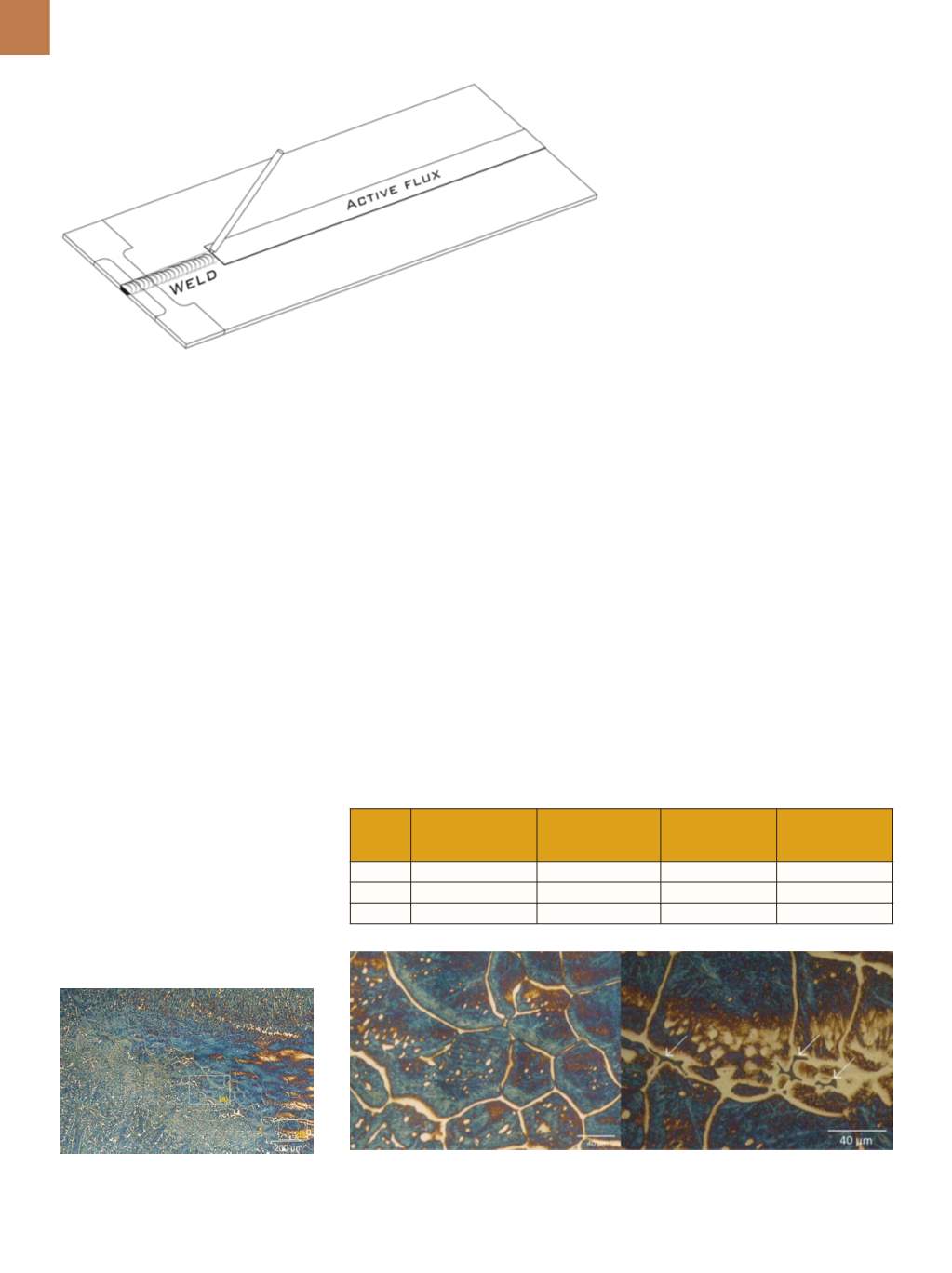
Fig. 3 —
Weld diagram shows the welding procedure and location of the tensile samples taken.
Fig. 4 —
Polarized LOM of Weld 1 shows the
weld and reaustenitized regions. Etched with
7% aqueous Na
2
S
2
O
5
.
Fig. 5 —
From left to right, detail (a) of Weld 1 as marked in Fig. 4 shows grain growth and segre-
gations within the reaustenitized region of Weld 1; Detail (b) of Weld 1 as marked in Fig. 4 shows
porosity at the fusion zone boundary. Etched with 7% aqueous Na
2
S
2
O
5
.
Weld 3 resulted in the greatest tensile
strength of 1578 MPa.
DISCUSSION
Four kinds of retained austenite
appear in the weld microstructures,
which vary in scale as well as chemical
composition: thin films in between the
bainitic ferrite subunits; micron-size
blocks in between the bainitic sheaves;
coarse austenite within the interden-
dritic regions of the weld bead, which is
up to tens of microns in thickness; and
coarse austenite blocks formed within
the reaustenitized zone, which are up
to 10 µm thick. It is widely known that
the properties of carbide-free bainitic
steel strongly depend on the mechani-
cal stability of retained austenite
[9]
. This
stability is profoundly influenced by its
size
[10]
, whereby coarse regions trans-
form into brittle high carbon marten-
site under lower stresses than their fine
counterparts
[11]
.
Very coarse austenite regions
within the HAZ must be prevented, as
their presence is unacceptable. This can
be accomplished by controlling heat in-
put and optimizing the hot rolling treat-
ment. Whereas retained austenite with-
in the interdendritic regions cannot be
entirely avoided, it should be distribut-
ed as finely as possible and its volume
fraction kept low. As shown in Table 2,
the average amount of interdendritic
retained austenite changes propor-
tionally with heat input. However, the
relation is not linear, and it can be ex-
pected that the total amount cannot