



 18 / 58

edfas.org
ELECTRONIC DEVICE FAILURE ANALYSIS | VOLUME 19 NO. 2
18
lens is held at 3.8 kV (2b), which defocuses the beam so
that it can be refocused by the final stage of the lens (2c).
The focused beam enters the hollow spherical region,
which bends the beam to refocus it to a single point. The
outside of the region (labeled “3”) is held at 2.3 kV, which
guides the beam around the bend. The inside spherical
electrode (labeled “4”) is held at 0 V. The conical region
guides the ring-shaped beam to a single point, where it
strikes a secondmoderator. The outside of it (labeled “5”)
is held at 0 V, while the inside is at 780 V.
Finally, the beam strikes a second moderator
(labeled “7”), which has a distinct purpose from the first.
Undergoing two moderation steps with an efficiency of
10
−4
would severely detrimentally affect the intensity of
the beam; however, this is not what happens. For the
first moderation step, the positrons in a small segment
of the spectrum of positron energies are reduced to
thermal energies. In the secondmoderation, only a small
nonconservative process is introduced to a beam with
uniform energy to overcome phase space limitations
imposed by Liouville’s theorem that would prevent these
positrons frombeing focused into a collimated beam. The
re-emitted positrons then travel as a tightly focused par-
allel beam. The second moderator is reflection based.
[19]
MODERN POSITRON SPECTROSCOPIES
Crystal imperfections trap positrons differently
depending on the nature of the imperfection; there are
two categories of slow positron beam spectroscopies
capable of analyzing those differences. The first category,
positron lifetime spectroscopy, measures the length of
time between a positron entering the sample and annihi-
latingwith an electron. The lifetime of a positron in a solid
depends inversely on the local electron density. Different
types of defects have unique positron lifetimes that differ
fromthe lifetime of the positron in the bulk of thematerial.
A vacancy in the crystal lattice traps positrons, because
the lack of a nearby nucleus increases the negative charge
density in the area and becomes a positron trap. While
the region has a greater local negative charge, there are
actually fewer electrons there because of the absence of
core-shell electrons around the nucleus. This leads to a
longer lifetime for trapped positrons. The number of dif-
ferent lifetimesmeasuredand their relative intensities give
information about the types and relative abundances of a
variety of defects. Positron lifetime spectroscopy requires
a start signal for the creation of each positron and a stop
signal for each annihilation. The most straightforward
method is to use an intermittent or pulsed beam. For
positrons created in pulsed bunches in an accelerator,
lifetime spectroscopy is ideal. When using a radioactive
source to generate the beam, however, onemust chopand
bunch the continuous supply ofmonoenergetic positrons.
The other main category of slow positron beam tech-
niques measures the positron’s momentum. Positrons
penetrate a samplematerial toameandepthproportional
to their energy. They lose energy by undergoing inelastic
collisions until they thermalize to a Maxwell-Boltzmann
distribution, that of a classical gas. The thermalized
positrons then diffuse through the material until they
annihilate with an electron. This annihilation releases
two 511 keV photons back-to-back in the reference frame,
where their net momenta are zero. Because the electrons
in the sample aremovingmuch faster than the positrons,
that reference frame is likely to be moving relative to
the laboratory. In early experiments, the difference in
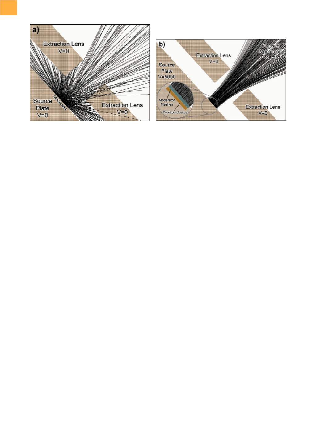
Fig. 8
Efficiency of the collection optics. (a) Uniform distribution of positron emission when there is no voltage difference
between the source and the extraction lens. (b) 100% collection efficiency when the source is biased at 5 kV against the
extraction lens