


 17 / 58

edfas.org
1 7
ELECTRONIC DEVICE FAILURE ANALYSIS | VOLUME 19 NO. 2
BEAM TRANSPORT
The transport of the monoenergetic beam is nearly
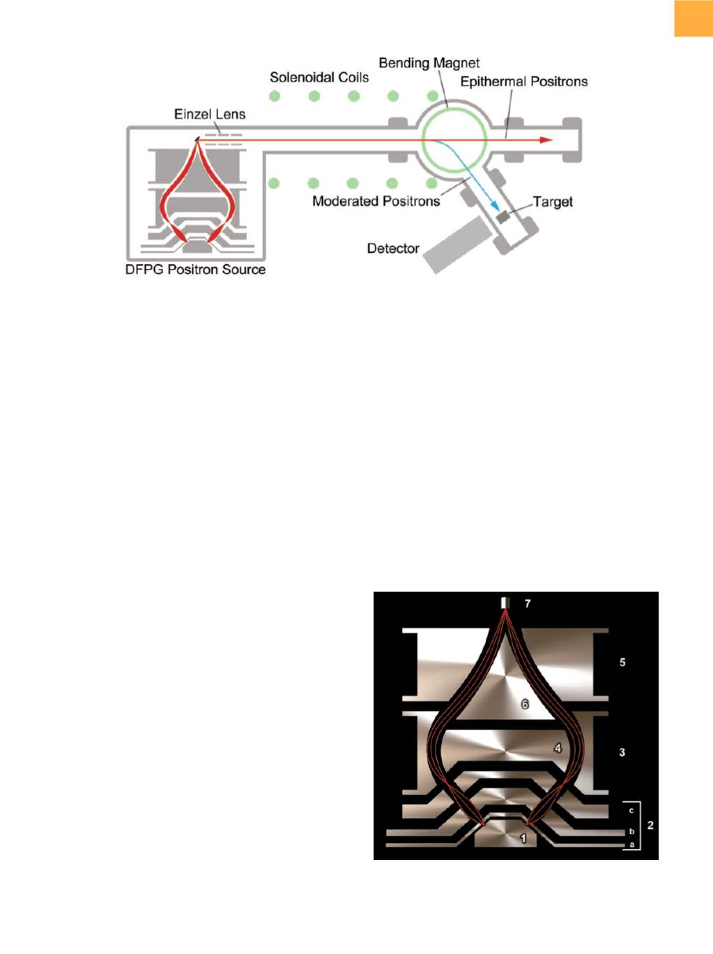
completely lossless. Figure 6 shows the arrangement of
the beam. The beam is directed through a vacuumof 10
−6
torr or less and is guidedby toroidalmagnets that keep the
beamcollimated for themeter ormore distance in spite of
small transversemomenta. There is also a Helmholtz coil,
which is necessary to cancel the effects of the magnetic
field of the Earth. Magnets are used to bend the moder-
ated beam to send it on a different trajectory. Positrons
that are unmoderated or only partially moderated have
a larger turning radius than positrons that are moder-
ated. When the moderated beams go around the bend,
the others are instead directed toward a shielded beam
dump. The beam is then passed through an electrostatic
voltage drop, which accelerates the positrons. This drop
can be varied to alter the energy of the positrons in the
beam and thus their penetration depth. The beamfinally
passes through an aperture to remove fringe positrons,
thus forming a tight beam that strikes the target sample.
The target sits at least a meter from the source to reduce
background radiation at the detectors.
DEFLECTION FOCUSING
POSITRON GUN
The problem of increasing the intensity of the slow
positron beamhas been addressedwith the development
of the DFPG. This device uses advancements in modera-
tor mesh technology, in combination with a much larger
source ring, and a second moderation step to produce a
collimated beamsimilar to those created from traditional
22
Na sources, only with a greater intensity. Figure 7 shows
the diagram for the device.
Instead of the standard small source (2mmdiameter),
the DFPG uses a ring-structure arrangement to increase
the amount of source that is available to the beam by
2 orders of magnitude. Directly above the source is the
moderator, which consists of layered tungsten meshes.
This is collectively held at 5 kV and is labeled “1” in Fig. 7.
The voltage difference between the source and the extrac-
tion lens draws the emitted positrons forward from the
meshes, as shown in Fig. 8.
Once the positrons are emitted from the moderator
meshes, they enter the focusing layers of the DFPG. The
next three stages constitute amodifiedEinzel lens, labeled
“2” in Fig. 7. The first and last stages (2a and 2c) are held
at 0 V. The large voltage difference between the source
and the first stage of the lens (2a) pulls the moderated
positrons forward to forma beam. The center stage of the
Fig. 6
Beam line used for the deflection focusing positron gun
Fig. 7
Deflection focusing positron gun shown in cross-
sectional profile, with the individual parts numbered
for reference. The beam path is outlined in red.