


 12 / 58


edfas.org
ELECTRONIC DEVICE FAILURE ANALYSIS | VOLUME 19 NO. 1
12
MOBILE IONS IN ICs
The following three corrective actions havemade such
failures rare:
• Cleaner fabrication minimizes mobile ions.
• Processes include phosphorus glass, which “getters”
mobile ions. That is, phosphorus glass effectively locks
mobile ions safely away from critical oxide.
• Nitride and metal elements act as barriers to mobile
charge. Mobile ions cannot penetrate nitride films.
While steps to avoid IC failure are overwhelmingly
successful, it is clear that under unique conditions, mobile
ions could cause fatal leakage between isolated
n
-wells or
threshold shifts in MOS transistors. Mobile ions must be
considered a possible cause for bake-recoverable failures.
Look for cracks or misalignments that defeat steps to
control mobile charge.
OXIDE-TRAPPED CHARGES
Three categories of charges are associated with traps
or oxide defects:
• Fixed charge (Q
f
):
Incomplete oxidation of silicon leaves
a positive charge by failures of very early
PNP
devices
approximately 2 nm above the interface to the silicon.
Crystal structure makes the fixed charge lower for 100
silicon material than for 111 material. (
Q
f
was labeled
Q
ss
in early publications.)
[2]
• Interface charge (Q
it
): Q
it
is similar to
Q
f
if located at the
interface to the silicon, and it can be either positive
or negative. Electrons and hydrogen can be trapped
at these locations. This charge is sensitive to oxida-
tion details, such as temperature and the presence of
oxygen. A hydrogen anneal is often used to minimize
charge. Process variations to achieve a high-k dielec-
tric, such as addition of hydrogen and hafnium, also
affect
Q
it
.
• Trapped oxide charge (Q
ot
):
A broken silicon-oxygen
bond can occur anywhere in an oxide film. Traps can
be created during oxide growth or at any later time.
High-energy events such as radiation, plasma process-
ing, hot carrier injection, and simple oxide current
can create oxide traps, which present a preferred path
for oxide current. Thus, traps are involved in time-
dependent dielectric breakdown and electrostatic
discharge failure.
OXIDE FAILURE
As suggested previously, gate oxides are susceptible in
many ways to failure or degradation due to an excess of
oxide traps. Gate leakage or threshold changes can cause
function failures, timing failures, andmany other failures.
Identifying the cause of failure depends on identifying
exactlywhat failed, when it failed, andunder what circum-
stances. A considerable amount of data may be required
to conclude the cause of failure. More than a single failure
is required to accomplish this.
Plasma etching is known todamage oxides.
[3]
Voltage is
built up due to unequal exchange of positive and negative
ions. The degree of charging is a function of processing
variables. Circuit layout is critical. Layout controls the
exposure of gate oxides to damaging discharge current.
The key to analysismay be the observation that damaged
oxide is, or is not, connected to material that acts as an
antenna for charge. Design rules limit the amount of poly
or metal allowed to act as an antenna for gate oxide.
[4]
Diodes are often added solely to protect gate oxide by
shunting plasma-induced current away from vulnerable
oxide.
Gate oxides are degraded by current flow from any
cause. Excess voltage can be caused by circuit configura-
tion or external probing. In addition, excess voltage can
be caused by reactive ion etch during decapsulation for
failure analysis.
REFERENCES
1. A.S. Grove: “The Origin of Channel Currents Associated with
P
+
Regions in Silicon,”
IEEE Trans. Electron Dev.,
June 1965,
12
(12), pp.
619-26.
2. B. Deal et al.: “Characteristics of Surface State Charge (
Q
ss
) of
Thermally Oxidized Silicon,”
J. Electrochem. Soc.,
1967, pp. 266-77.
3. L. Pantisano et al.: “Experimental Approach to Evaluate Plasma
Damage inMNOS and PMOS Devices,”
Int. Reliab. Phys. Symp. (IRPS),
1999, pp. 375-80.
4. K.P. Cheung:
Plasma Charging Damage,
Springer, 2012, p. 316.
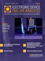
Fig. 5
Schematic cross section showing successful channel
stop. Electric field is eliminated by guard ring.