


 7 / 58

 edfas.org
7
ELECTRONIC DEVICE FAILURE ANALYSIS | VOLUME 18 NO. 2
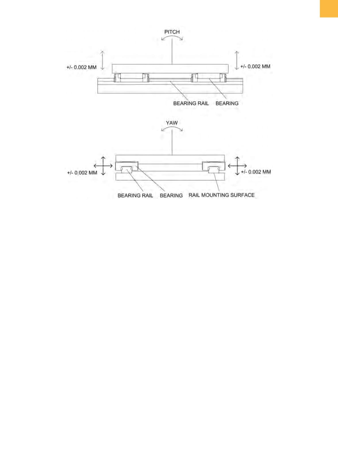
Fig. 4
Linear bearing arrangement and the effects of runout
position, and the horizontal runout adds directly to the
Y
axis uncertainty.
PROCESSES FOR BACKSIDE THINNING
Backside thinning of a sample often requires the
removal of encapsulant, die-attach pad, and die-attach
adhesive. These processes are usually defined by the
position of the extreme edge of the cutting tool. As the
tool is rotating, the eccentricity of the tool and spindle
and the actual tool diameter all determine the location
of the extreme cutting edge. A typical end mill will have
a diameter tolerance of ±13 µm
[7]
or more. A very good
spindle and collet for securing the end mill to the spindle
may have a runout of ±7.6 µm.
[8]
The runout is a func-
tion of the concentricity of the spindle to the collet axes.
The end mill may also have runout that results from the
cutting edges not being coaxial with the shank. All of this
makes the uncertainty of the edges of the machined area
±20 to 25 µm from tool and spindle tolerances alone. A
desire to define themachined area to ±1 µm requires that
the running tool and spindle inaccuracies be taken into
account. This can only be done in situ. That is, an operator
must adjust the machined area during machining. Once
this is done, the repeatability of the
X-Y
movement only
needs to be within the desired positional tolerances to
produce an acceptable result.
Adjusting tool position and travel during operation
is problematic. Attempts to have video viewing during
operation are often obscured by slurry and swarf. Because
the video camera cannot viewdirectly down the tool axis,
there must be some parallax. The parallax makes any
Z
-positional movement also appear to be a movement
in the
X-Y
plane. Moving the sample to a viewing position
creates measurement and correlation problems.
When thinning a die to a measured surface contour,
X
- and
Y
-positional uncertainties have an effect on the
Z
position due to the surface profile. The maximum slope
of the profile, multiplied by the
X-Y
-positional uncertainty,
adds to the
Z
axis positional uncertainty when determin-
ing the overall profile reproduction uncertainty. A slope
of 20 µm/mm will add to the
Z
axis uncertainty as the
X-Y
-positional uncertainty (in mm) times the 20 µm/mm
slope. Therefore, a ±5 µm
X-Y
uncertainty will introduce
an additional
Z
axis uncertainty of 0.1 µm.
WHAT IS REQUIRED
The system repeatability must be equal to or slightly
less than the desired positional accuracy. If a machined
pattern must be maintained at ±1 µm, then the repeat-
ability of
X-Y
positioningmust be 1 µmor less. A resolution
of less than one-half of the positional uncertainty is