


 6 / 58

 edfas.org
ELECTRONIC DEVICE FAILURE ANALYSIS | VOLUME 18 NO. 2
6
In addition to the temperature effects, there is a toler-
ance on the zero position. This is a result of the switches
used to detect when an axis is at the zero position. These
switches may be mechanical, optical, or magnetic. No
matter which type of switch is used, it will have some
level of uncertainty that results in uncertainty in the zero
position.
The resolution of themachine is a function of howwell
the scale can be measured by the linear encoder. A good
encoder can provide positional resolution of 50 nm, but
the accuracy is a function of the scale.
[5]
A typical optical
scale will have a nonlinearity of 0.005 mm per meter of
travel and a thermal expansion coefficient (
T
c
) of themate-
rial towhich it ismounted.
[5]
Steel has a
T
c
of 11.5 ppm/°C,
and the
T
c
for aluminum is 23 ppm/°C. A 100-mm-long
scale will change 0.0023mm/°C. All of this is additive. The
uncertainty due to scale resolution adds to the nonlinear-
ity, zero position uncertainty, and the thermal variations
of the scale. With a typical ±2° variation in temperature
and a 100-mm-long scale, zero uncertainty of ±0.5 µm,
and the scale nonlinearity, the positional uncertainty is
±5.6 µm. This is 110 times greater than the encoder
resolution.
THE CONCEPT OF UNCERTAINTY
Uncertainty is the ultimate tolerance on any positional
move. The factors that affect uncertainty are repeatability,
accuracy, geometric factors, interaction between the axes
of movement, and environmental effects. The repeatabil-
ity, as shown in Fig. 2, will drift in position resulting from
temperature effects, and the pattern center will move as
a result of the other factors. Repeatability will always be
less than uncertainty.
THE GEOMETRY OF MACHINE
PERFORMANCE
All machines involve linear and rotational movement.
Mostmachines involvemultiple-axismovements. Thegeo-
metric relationship of the axes to each other will directly
affect the position in the other axes as movement takes
place. If the
X
and
Y
axes are at 89° instead of 90°, a move
in either axis will produce a positional shift of 1.745%
of the move in the other axis. Resolution, accuracy, and
repeatability in one axis are meaningless if the axes are
not truly orthogonal. If the
Z
axis is not normal to the
X-Y
plane, changes in
Z
position produce changes in the tool
tip’s position referenced to the
X-Y
plane.
Determining axis uncertainty requires knowing the
geometric relationships of all three axes and the rotational
axis of the tool. This requires the manufacturer to specify
the orthogonality of the axes to each other and the nor-
mality of the
Z
axis and spindle to the
X-Y
plane (Fig. 3).
Although the geometric variables donot directly affect the
repeatability, the interaction in position from geometric
inaccuracies makes each axis’s real position a function of
the other axes’ positions.
In addition to the geometric problems, the runout of
each axis also must be considered. The linear bearings
or linear positioner used in each axis have runout in the
perpendicular axes. A typical precision-grade profile linear
bearingwill have 2µmrunout in the vertical andhorizontal
axes.
[6]
That is, as the linear bearing ismoved, it canmove
a small amount vertically and horizontally. Even super-
precision bearings have a runout of 1.5 µm. The runout in
one axis adds directly to the positional uncertainty of the
other two axes. The runout also produces rotation about
each axis as a functionof the separationbetween the bear-
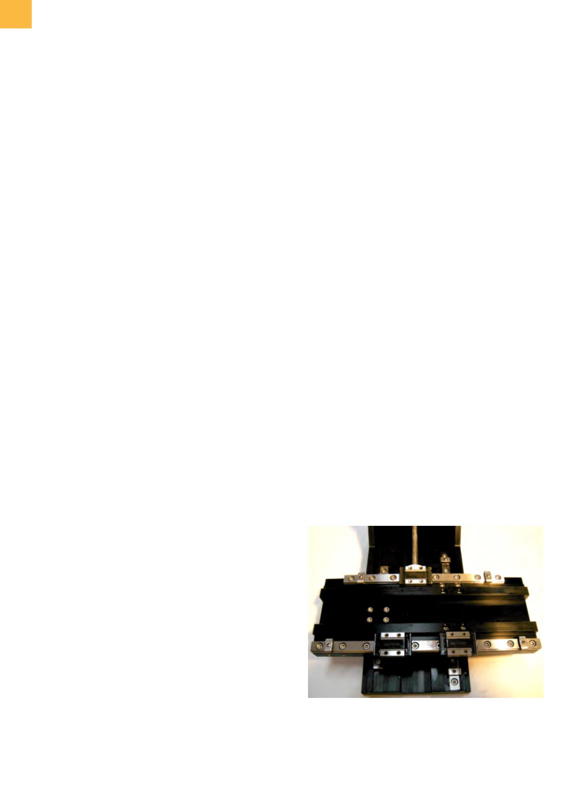
ings used. As an example, Fig. 4 shows a single axis using
four linear bearings on twoprofile rails in a square pattern:
• A 2 µmhorizontal and vertical runout in
X
will produce
±2 µmmovement in the
Y
and
Z
axes.
• The rotationpossible is a result of +2 µmonone bearing
and −2 µm on another. The pitch is then a function of
the bearing spacing. The yaw becomes a function of
the rail spacing.
• The pitch and yaw affect true position in all three axes
according to the geometric relationships and the dis-
tance from the sample to the axis plane.
All of these variables directly add to other sources
of positional uncertainty. Vertical runout on the
X
axis
bearings adds directly to the uncertainty of the
Z
axis
Fig. 3
Typical
X-Y
movementmechanismwith the
X
axis stage
removed. There are three bearings instead of four
on each axis, although the runout and orthogonality
effects are the same as in the text.