


 5 / 58

 edfas.org
5
ELECTRONIC DEVICE FAILURE ANALYSIS | VOLUME 18 NO. 2
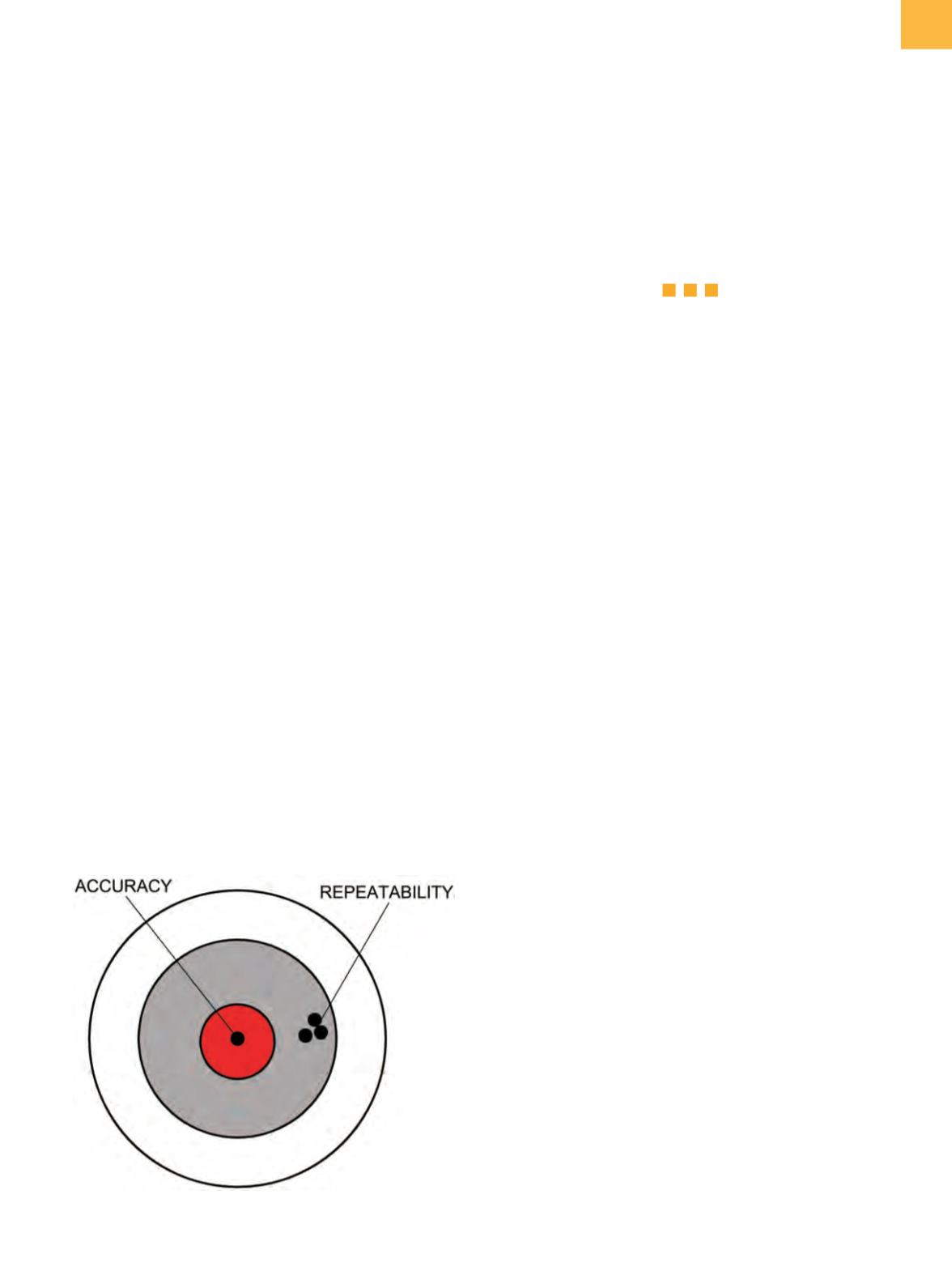
The easiest way to illustrate the difference between
accuracy and repeatability is to refer to the rifle target in
Fig. 2. A tight grouping is repeatability.
In addition to these terms, the geometric properties of
parallelismandorthogonality determine the performance
of a mechanical system.
Simple mechanical devices used for sample prepara-
tion, such as diamond saws, dimplers, and many others,
have easy-to-understandmechanical systems, andas long
as they are properly maintained and calibrated, they will
perform their designated tasks. With simpler machines,
if the quality of the results is lacking, then service and
adjustment are required.
A more complex machine is the flat lapper. There are
two basic types of lappers: open face, where the sample
being lapped is mounted to a fixture that is placed inside
or attached to a rotating ring, and lapperswith amast that
supports a sample holder and provides sample rotation
and movement across the lap surface. Either type can
use abrasive lapping films or a slurry feed system. Critical
parameters on a lapper include axial runout, lap flat-
ness, and the parallelism of the rotational, scan, and lap
spindle axes. The axial runout is the variation in height of
the lap surface at the edge as the lap rotates. For control-
lable results with any lapper, the lap should be flat and
not have axial runout. The parallelism of the rotational,
scan, and lap spindle axes determines the surface shape
of the sample. Axial runout will produce scalloping at the
sample edges. Lack of parallelism of the rotational axis
will produce a conical surface. Lack of parallelism of the
scanaxiswill produce a spherical surface. Aligningall three
axes is difficult to impossible, depending on themachine,
but it is necessary if die delayering is to be done. A 1 or
2 µm axial runout on the lap, or the rotational axis not
being parallel to the spindle, or the scan axis not being in
linewill produce a nonplanar result. The geometries of the
inaccuracies are easy to calculate. A 0.02 mrad misalign-
ment of the sample holder rotational axis will produce a
10 mm
2
sample with the corners more than 100 nm lower
than the center. When delayering, this conical shape can
make the results unacceptable. Accuracy depends on
set-up adjustments for the machine. Ongoing successful
sample preparationdepends onmaintaining these adjust-
ments. Periodic adjustments may need to be performed
by a specially trained technician or engineer.
THREE-AXIS-MOVEMENT MACHINES
There are machines available for die thinning or
delayering that have movement in three axes as well
as a rotating spindle that holds the tool. It is with these
machines that the concepts of accuracy, resolution, and
repeatability are most relevant. These machines move a
tool over the die surface by moving the sample in the
X
and
Y
axes and moving the tool in the
Z
axis.
In linear positioning systems, such as used on these
machines, the linear motion is commonly produced with
a lead screw, and the position is measured by a linear
encoder and scale. A computer controls themotor driving
the lead screw so that the encoder gives the desired posi-
tion value. The encoder has specifications for linearity and
resolution and, occasionally, zero reference repeatability.
In a numerically controlled machine, there is always a
reference or zero point that is periodically checked to
establish a positional reference. This is almost always at
the extreme travel of the machine in
X
or
Y
, while most
work is done near the center of the travel. The temperature
effects on the linear encoder scale then alter all positional
values by a function of the total travel from the zero point.
This means that the longer the travel, the greater the zero
shift produced by temperature changes. A machine with
200 mm of travel will have twice the thermal zero shift as
a machine with 100 mm of travel.
Fig. 2
Accuracy as opposed to repeatability
“IN LINEAR POSITIONING SYSTEMS,
SUCH AS USED ON THESE MACHINES,
THE LINEAR MOTION IS COMMONLY
PRODUCED WITH A LEAD SCREW, AND
THE POSITION IS MEASURED BY A LINEAR
ENCODER AND SCALE. ”