


 4 / 58

 edfas.org
ELECTRONIC DEVICE FAILURE ANALYSIS | VOLUME 18 NO. 2
4
EDFAAO (2016) 2:4-10
1537-0755/$19.00 ©ASM International
®
A DISCUSSION OF THE MECHANICAL LIMITATIONS
OF MACHINERY USED FOR
SAMPLE-PREPARATION PROCESSES
Kirk A. Martin, RKD Engineering
Nancy Weavers, Left Coast Instruments
kirk@rkdengineering.comor
nweavers@lcinst.comINTRODUCTION
Many semiconductor failure analysis sample-prepara-
tionprocedures requiremechanical machining processes.
These processes include removing encapsulant, removing
heat spreaders, cutting of the sample for cross sectioning,
package substrate printed circuit board delayering, die
thinning by grinding and polishing, die delayering, and
many others. The machines used for mechanical sample
preparation have ultimate limitations based on the
machine’s accuracy, resolution, repeatability, and envi-
ronmental effects. These limitations can/may affect the
results of the sample-preparation process. Limitations to
ultimate performance include the intrinsicmachine reso-
lution, accuracy, and repeatability of the tool-positioning
system as well as tolerance limitations resulting from the
tool bits, pads, and other consumable components. Note
that a
tool,
as used here, is an end mill, a grinding tool, a
saw blade, or other simple functional device. A
machine,
or machine tool, is what utilizes a tool to perform a spe-
cific task. A milling machine is a machine. The end mill it
uses is a tool.
A BRIEF DISCUSSION OF TERMS
The dictionary definition of
accuracy
is “the extent
to which a given measurement agrees with the standard
value for that measurement.”
[1]
The standard used as the “standard value” generally is
a National Institute of Standards and Technology (NIST)
traceable length standard with an absolute tolerance
defined by the reference standard and class. A length ref-
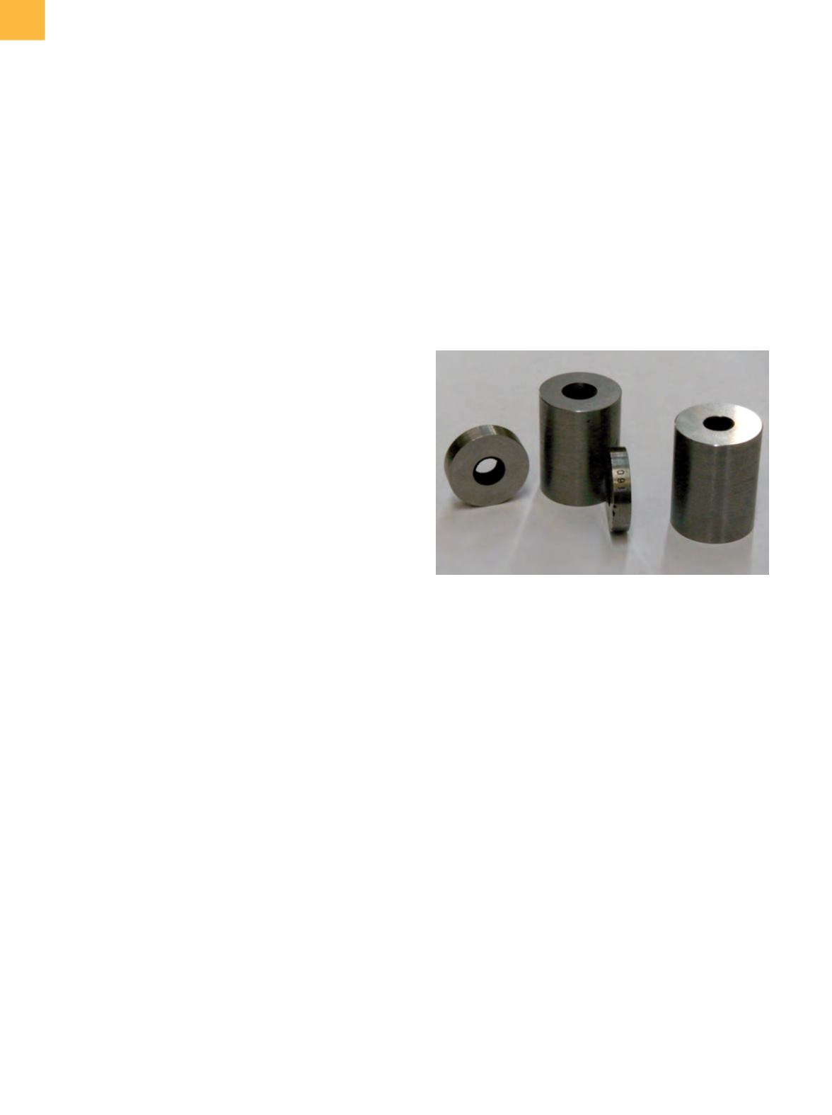
erence is normally a gauge block. A gauge block is a piece
of metal having flat and parallel opposing gauge surfaces
(Fig. 1). A grade 2 NIST 100 mm gauge block matches the
NIST reference standard to+0.0003/−0.00015mm, but only
at the standard conditions:
[2]
• Temperature = 20 °C (68 °F)
• Barometric pressure = 101,325 Pa (1 atm)
• Water vapor pressure = 1333 Pa (10 mm of mercury)
• CO
2
content of air = 0.03%
The steel of the gauge block expands with increasing
temperature at a rate of 11.5 ppm/°C.
[2]
A 1° increase in
temperature of the 100 mm gauge block will result in a
dimensional change of 0.00115mm, or nearly three times
its specified accuracy.
The dictionary definition for
resolution
is “the fineness
of detail that can be distinguished.”
[3]
When taking any
measurements, there is a limiting fineness of the mea-
surement, as determined by themeasurement reference.
When using a ruler marked with only 1 mm increments,
a length can only be determined to the nearest 1 mm. If
the ruler’s overall length is off by 10%, the measurement
can still be taken to a 1 mm resolution. Resolution is not
a function of accuracy.
The definition of
repeatability
is “the variation inmea-
surements taken by a single person or instrument on the
same item and under the same conditions.”
[4]
Fig. 1
Representative cylindrical gauge blocks