
A D V A N C E D
M A T E R I A L S
&
P R O C E S S E S |
N O V E M B E R / D E C E M B E R
2 0 1 6
6 3
FEATURE
13
choice when shorter heat times/high production rates are
desired. Heating time can be as short as two seconds, but is
typically four to eight seconds. Sufficient rotation is critical
with single-shot inductor design; at least 10 full rotations per
heat cycle is desired. Spray quenching can begin immedi-
ately after austenitization is complete, or after a short delay.
The duration of quench delay can range from a fraction of a
second to a few seconds depending on the geometry of the
component, material chemical composition, and hardness
pattern specification.
COMPUTER MODELING SPECIFICS
The current production environment does not allow
the luxury of process design via trial and error. Computer
simulation enables induction heating specialists to quickly
determine process details, which could be costly, time con-
suming, anddifficult or impossible to resolve experimentally.
Simulation enables prediction of how different interrelated
and nonlinear factors could impact the transitional and final
thermal conditions of the heated component. It also helps
determine what must be accomplished to improve process
effectiveness to establish the most appropriate process rec-
ipes. Computer modeling provides a comfort factor when
designing new systems, avoids unpleasant surprises, short-
ens the learning curve, and reduces development time.
Today, most software programs are not capable of
modeling single shot hardening. However, FEA software
developed by Dante Solutions in combination with propri-
etary subroutines for Flux-3D developed by Inductoheat
enable taking into consideration all critical features of the
induction hardening process
[2]
.
MODELING INDUCTION HARDENING
OF ASTEEL SHAFT
Consider a case study of induction hardening of an AISI
4140 alloy steel shaft with shoulders and numerous changes
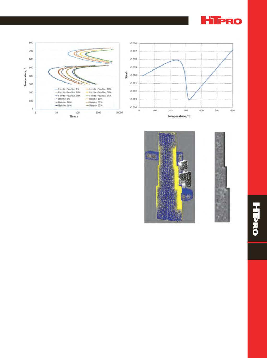
Fig. 2 —
TTT diagram (a) and dilatometry strain curve (b) of martensite transformation for AISI 4140 generated fromDante database.
Fig. 3 —
Finite element models: (a) electromagnetic model used
by Flux-3D, and (b) 2D axisymmetric model used by Dante.
in diameter. Phase transformations occur during induction
heating and spray quenching. The surface of the part trans-
forms to austenite during heating, and during quenching,
austenite can transform to ferrite, pearlite, bainite, or mar-
tensite depending on the cooling rate. Accurate descriptions
of phase transformations and mechanical properties of
individual phases are required for thermal stress analysis
[3]
.
Figure 2(a) shows the TTT diagram of 4140 generated from
the Dante database. The TTT diagram is not used in Dante
models directly, but the analytical phase transformation
models and database contain all TTT diagram information.
Figure 2(b) shows a dilatometry strain curve during marten-
site formation under continuous cooling. The curve provides
themartensite start temperature (M
s
), martensite finish tem-
perature (M
f
), transformation strain, and coefficients of ther-
mal expansion (CTE) for austenite and martensite. Because
(a)
(b)
(a)
(b)


