


 64 / 82

A D V A N C E D M A T E R I A L S & P R O C E S S E S | N O V E M B E R / D E C E M B E R 2 0 1 6
6 4
FEATURE
14
the cooling rate during spray quenching is severe, the main
transformation in this study is austenite to martensite.
Using Flux-3D, the electromagnetic problemwas solved
and 3D heat source distribution was obtained at different
heating stages. The finite element model is shown in Fig. 3(a).
Calculated power distribution from the Flux-3D model was
mapped into the Dante model for thermal, phase transfor-
mation, and stress analyses; the Dante mesh is shown in
Fig. 3(b). After inductionheating, the shaftwas sprayquenched
usingapolymersolutionwithoutdelay.Differentfiniteelement
mesheswere used for the Flux andDantemodels.
MAPPING FROM FLUX-3D TO DANTE
Copper inductor profiling was optimized and the most
appropriate locations for magnetic flux concentrators were
determined to address changes in shaft geometry. During
the hardening process, the shaft was positioned inside the
inductor with a rotation rate of five rotations/second, and
a total heating time of five seconds, which translates into
25 full rotations during the heating cycle.
Because temperature distribution is relatively uniform
circumferentially in the shaft, a 2D axisymmetric model was
used in Dante to model temperature, phase transforma-
tion, and stress evolution during heating and quenching.
Power distribution in terms of time predicted by Flux-3D
was mapped into the Dante heat treatment model. A special
mapping subroutine was developed because different finite
elementmesheswere used in the Flux-3DandDantemodels.
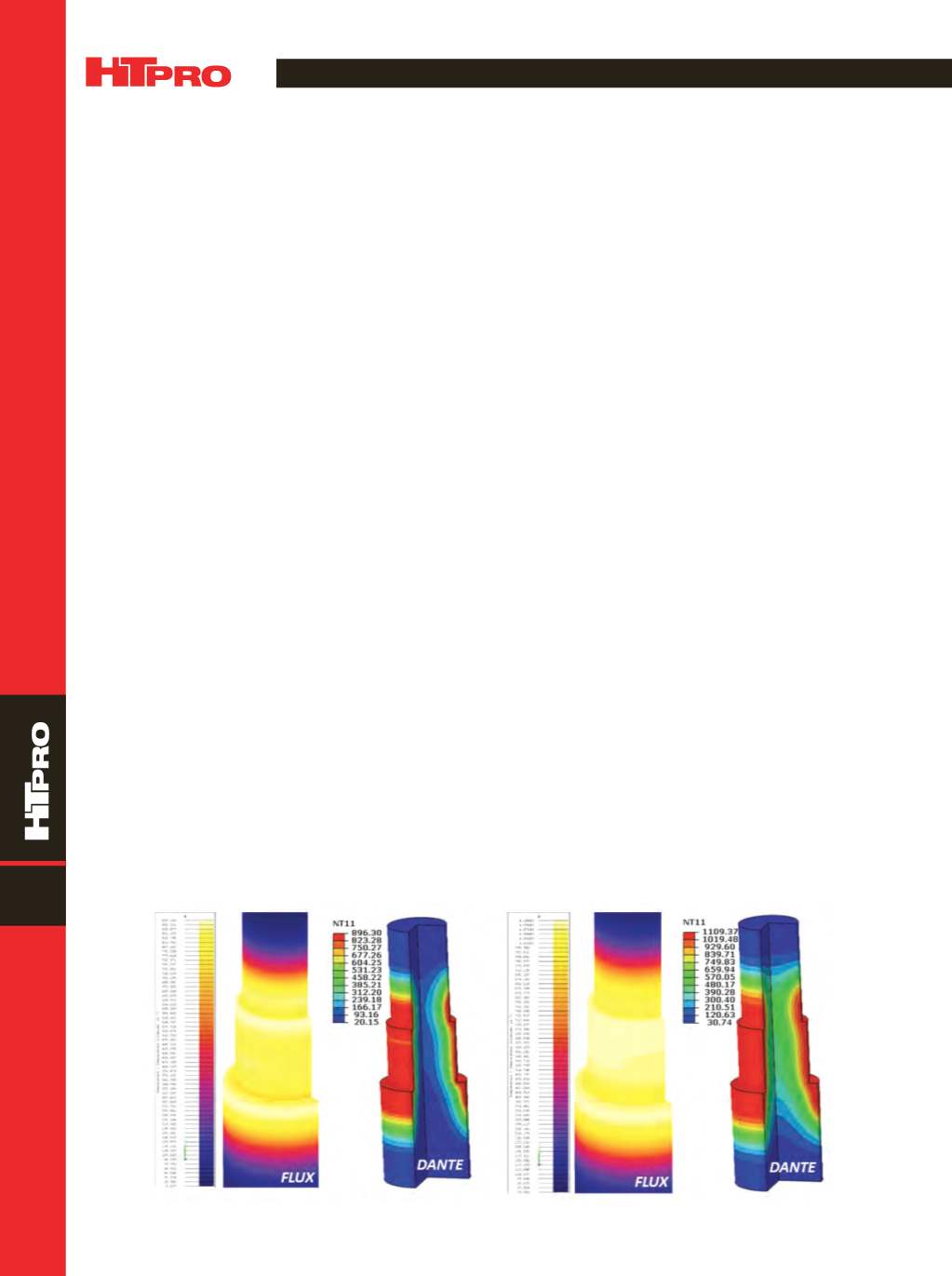
A comparison of temperature profiles projected by Flux-3D
and Dante reveals good correlation (Fig. 4).
STRESS AND PHASE TRANSFORMATION
MODELING USING DANTE
Temperature, austenite pattern, axial displacement,
radial displacement, and hoop stress distributions after two
seconds of heating are shown in Fig. 5. At the early stage of
heating before the surface transforms to austenite, the sur-
face is under compression due to thermal expansion. After
the surface transforms to austenite, the stress decreases to
amagnitude close to neutral. Compression occurs under the
austenite layer due to thermal expansion, with tensile stress
in the core to balance the stress.
Figure 6 shows predicted results at the end of the five
seconds of heating; the austenite layer is approximately
5 mm deep. Surface temperature is about 1100°C, and the
radial displacement of the heated region is about 0.2 mm.
After heating is complete, the shaft is spray quenched
using a 6% polymer solution; a convection coefficient of
15 KW/(m
2
K) is applied on the shaft surface of the FEA model
to represent the spray quench. After two seconds of quench-
ing, surface temperature is about 204°C, which is below the
M
s
(320°C) of AISI 4140, and martensite formation started
on the surface (Fig. 7). Surface stress shifts from tension to
compression due to the volume expansion that accompa-
nies martensite formation. Surface stress is tensile due to
thermal shrinkage caused by quenching prior to martensite
formation.
At about 10.4 seconds of quenching, almost all of the
austenite layer transforms to martensite (Fig. 8). The surface
temperature is about 70°C and core temperature is about
306°C. Hoop stress on the surface is about −310 MPa under
compression, a tensile stress of about 390 MPa is observed
under the austenitized layer, and the core is under slight
compression of -80 MPa.
Cooling of the core after phase transformation is com-
pleted has a significant effect on the change in stresses
in the shaft. Hoop stresses are −700 MPa at the surface,
+450 MPa at the case-core location, and +150 MPa in the core
after the shaft cools to room temperature (Fig. 9). Resid-
ual stress distribution affects shaft fatigue performance.
Fig. 4 —
Predicted temperature distributions between Flux-3D and Dante during induction heating at 2 s (a) and 5 s (b).
(a)
(b)