


 62 / 82

A D V A N C E D M A T E R I A L S & P R O C E S S E S | N O V E M B E R / D E C E M B E R 2 0 1 6
6 2
FEATURE
12
COMPUTER MODELING SINGLE-SHOT INDUCTION
HARDENING OF A POWER TRANSMISSION SHAFT
Computer modeling is used in induction hardening process design to improve component
quality including hardness, beneficial stress distributions, and reduced distortion.
Zhichao (Charlie) Li*
and
B. Lynn Ferguson, FASM,*
Dante Solutions Inc., Cleveland, and
Collin Russell*
and
Valery Rudnev, FASM,*
Inductoheat Inc., Madison Heights, Mich.
T
he automotive industry is implementing lightweight-
ing initiatives invehicledesign tomeetmorestringent
federal Corporate Average Fuel Economy regulations.
New component designs involve material removal result-
ing in complex geometries containing longitudinal and/
or transverse holes, grooves, shoulders, flanges, diameter
changes, undercuts, teeth, splines, andmore. Many of these
components with complex shapes are surface hardened
using induction hardening (Fig. 1). Four induction methods
routinely used are scan, continuous or progressive, static,
and single shot hardening
[1]
.
Irregularities in component geometry distort the mag-
netic field generated by an inductor, which can cause tem-
perature deviations, hot and cold spots, excessive shape
distortion, undesirable microstructures, grain boundary
liquation, and cracking. For example, scan hardening shafts
with large shoulders, multiple diameter changes of apprecia-
ble size, and other irregularities can produce severe nonuni-
formhardened patterns. Eddy current flow and temperature
fields should be evaluated to determine appropriate process
parameters and coil design to prevent cracking and mini-
mize distortion.
Steel shafts and shaft-like components are traditionally
induction surface hardened using scanning and single-shot
methods. In the single-shot method, the part rotates rather
than the shaft or coil moving relative to each other. The
entire region to be hardened is heated at the same time.
Single-shot inductors
typically control hardness pattern and
distortion better than scan and static hardening, particularly
for stepped shafts. A single-shot inductor consists of two
legs and two crossover segments. Crossover segments encir-
cle only half of the workpiece circumference, and induced
eddy currents primarily flow along the length of the part. An
exception is crossover segments where eddy current flow is
half circumferential. Longitudinal leg sections are profiled by
relieving selected regions of the copper inductor to accom-
modate workpiece geometrical features, such as changes in
diameter and undercuts.
Inductor configuration depends on factors such as
workpiece geometry, temperature uniformity, required
hardness pattern, and production rate. The designmust take
into account the tendency of certain geometrical features to
produce heat surpluses and/or heat deficits upon induction
heating. Required heat source control can be achieved by
adjusting the current-carrying face of the appropriate induc-
tor section, applying flux concentrators, and by varying the
inductor-to-workpiece gap. Determining the appropriate
inductor profilemight be cumbersome and time-consuming.
For critical applications, single-shot inductors are CNC
machined from solid copper to conform to the area of the
part to be heated. This type of inductor requires the most
care in fabrication because it usually operates at high power
densities, and workpiece positioning is critical with respect
to coil profile. Single shot hardening is also the preferred
*Member of ASM International
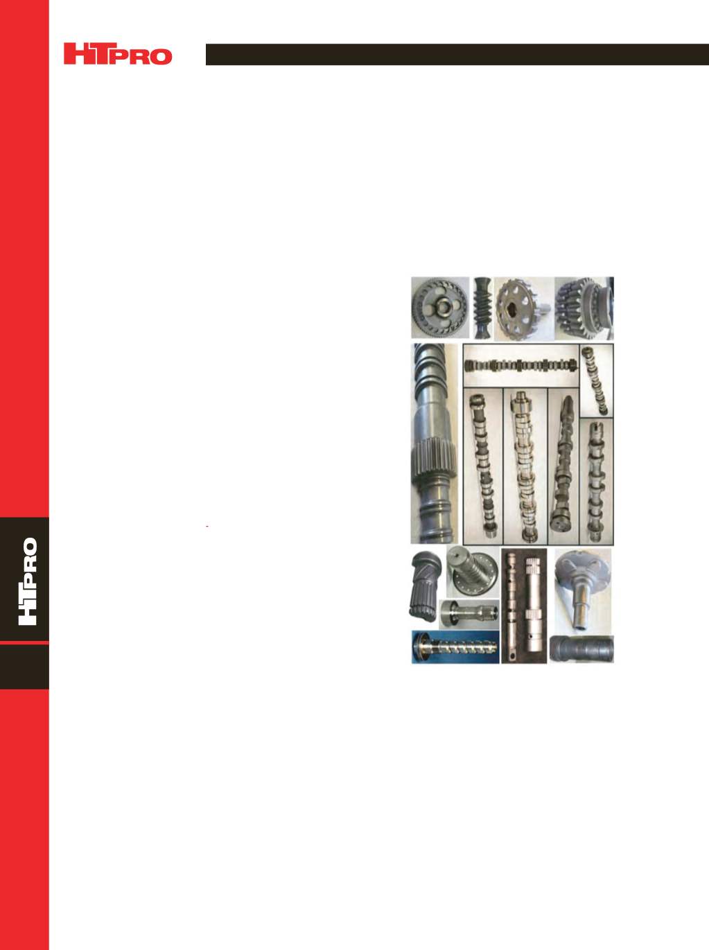
Fig. 1 —
Variety of complex geometry components that are rou-
tinely induction hardened.