


 57 / 102

A D V A N C E D
M A T E R I A L S
&
P R O C E S S E S |
O C T O B E R
2 0 1 5
5 7
17
FEATURE
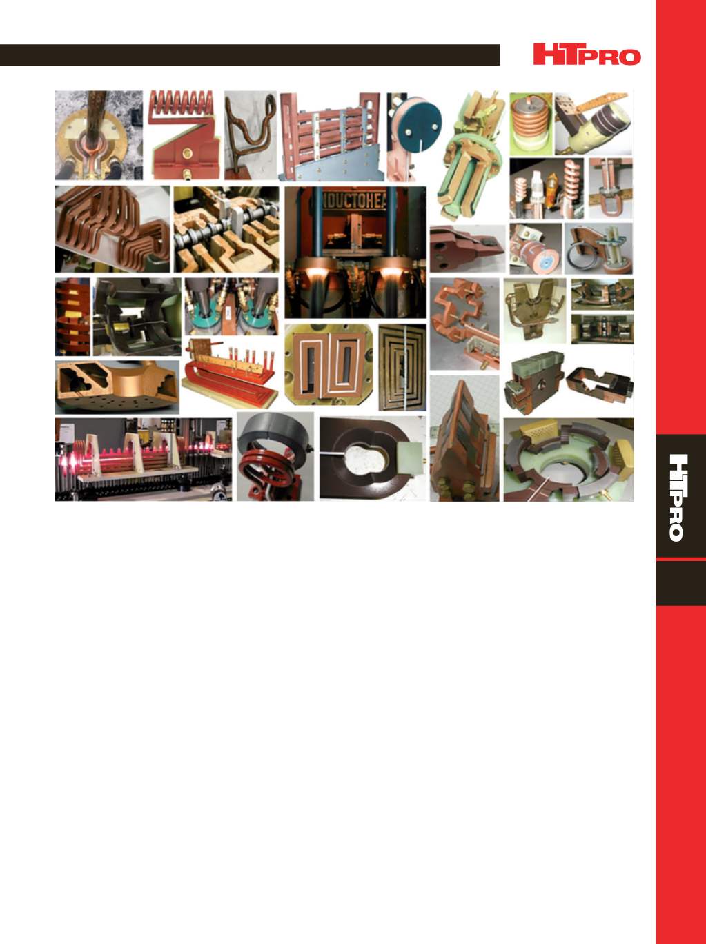
Fig. 1 —
Array of different induction coil designs.
spatial relationships, which produce inductors of the re-
quired shape and precision. Figure 2 shows a variety of fin-
ished and semifinished CNC-machined hardening inductors.
In the past, most of these inductors were fabricated by braz-
ing and banding coils. CNC machining is a superior method
to achieve accurate, robust inductors for use in automotive,
aerospace, defense and other industries where high process
repeatability is critical.
Brazing is completely eliminated with some CNC-
machined inductors, such as those used in Inductoheat’s
nonrotational SHarP-C processes for hardening crankshafts
and camshafts. Brazing is minimized in other applications,
used only to encapsulate water-cooling channels.
Some inductors, especially those used in selective
hardening, have very complex geometries. A computerized
3Dmetrology laser scanner is used to verify coil dimensional
accuracy and alignment precision within about 25 microns
(0.001 in.) after fabrication and assembly (Fig. 3).
CONVENTIONAL INDUCTORS
Steel shafts andshaft-like components areamongparts
that traditionally are induction hardened using scanning or
single-shot heat treating. With the single-shot method, nei-
ther the shaft nor coil move relative to each other; the part
typically rotates instead. The entire region to be hardened is
heated at the same time.
A single-shot inductor consists of two legs and two
crossover segments, also known as bridges or horseshoe
half-loops (Fig. 4). Crossover segments encircle only half of
the workpiece circumference, and induced eddy currents
primarily flow along the length of the part. An exception is
crossover segments where the flow of eddy current is half
circumferential. Longitudinal leg sections are profiled by
relieving selected regions of the copper to accommodate
workpiece geometrical features, such as changes in diame-
ter or irregularities. Section(s) of a single-shot inductor with
narrower heating surfaces facing the shaft increase induced
power density in desirable regions(s).
For a workpiece containing fillets, it is often necessary
to increase heat intensity in the fillet region to heat the great-
er volume ofmetal. Also, the largermetalmass in the proxim-
ity of the heated fillet and behind the region to be hardened
produces a substantial “cold sink” effect. This draws heat
from the fillet due to thermal conduction, which must be
compensated for by inducing additional heating energy in