
A D V A N C E D M A T E R I A L S & P R O C E S S E S | O C T O B E R 2 0 1 5
5 8
18
FEATURE
the fillet area. The required energy surplus can be achieved
by narrowing the current carrying face of the appropriate
section of the single-shot inductor. For example, if the cur-
rent carrying portion of the inductor heating face is reduced
by 50%, there is a corresponding increase in current densi-
ty, as well as the eddy current density induced within the
respective shaft region. According to the Joule effect, dou-
bling the induced eddy current density increases induced
power density by a factor of four. Also, attaching a magnetic
flux concentrator to certain areas of the hardening inductor
(Fig. 4) further enhances localized heat intensity.
The effects of intensifying heat generation in selected
areas of the shaft (i.e., excessive current densities in induc-
tor sections combined with intense heat radiation from the
workpiece surface) can cause localized copper overheating.
This promotes water vaporization and the formation of a
steam vapor barrier, which essentially functions as a ther-
mal insulator inside the water-cooling pocket. Thus, copper
cooling is severely restricted evenwhen it appears that there
is sufficient water-cooling flow and regardless of the use of
high-performance pumps. To help prevent overheating,
water-cooling pockets are placed as close as possible to the
current carrying face of an inductor. However, coil overheat-
ing can still occur and cause accelerated deterioration of the
copper surface, which speeds up the onset of inductor cop-
per cracking (due to stress fatigue and stress corrosion, for
example) and eventual premature coil failure. As a result, coil
life is often shortened to 22,000-24,000 heat cycles (industry
average). Therefore, the number of instances where coil cur-
rent density is increased should be kept to a minimum.
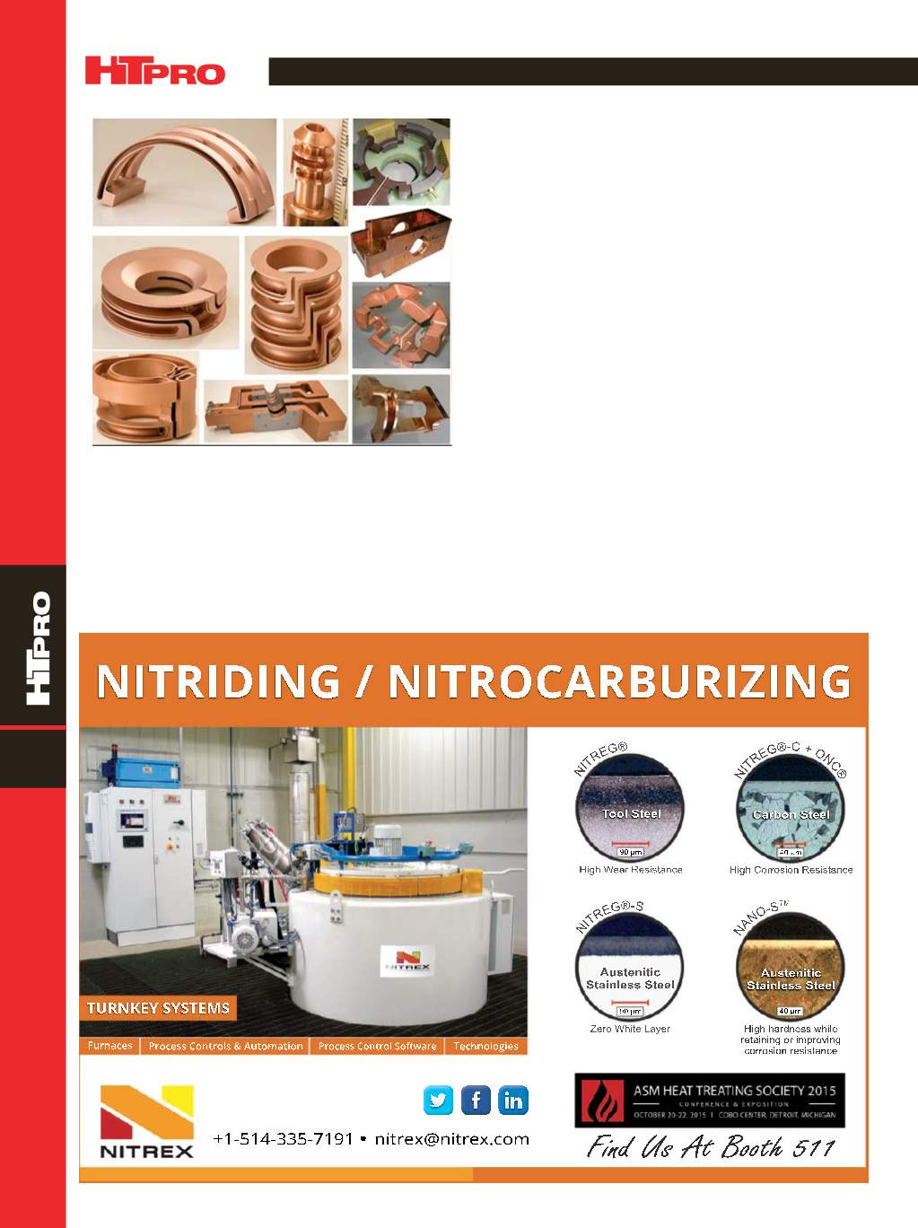
Fig. 2 —
Variety of finished and semifinished CNC-machined
hardening induction coils.


