


 24 / 62

 edfas.org
ELECTRONIC DEVICE FAILURE ANALYSIS | VOLUME 18 NO. 1
24
of short- and long-term reliability testing during package
qualification prior tomarket introduction. Oncemanufac-
turing and sales begin, mechanical testing is commonly
done on each material lot. Mechanical testing normally
consists of both wire bond pull testing and shear testing.
Because the weld areas for both the ball bond and the
second bond are several times larger in cross section
than the wire cross section, the pull test is not capable
of testing the strength of either bond (the wire breaks
first). However, it is capable of detecting very poor bonds,
wire damage, damage to the HAZ, or a second bond that
has been overdeformed and has a thin cross section at
the heel of the bond. The pull test measurement can be
understood from a simple resolution of forces. However,
once a history of data exists and statistical process control
has been established, the use of control charts can be a
very powerful quality tool. The shear test is capable of
measuring ball bond strength and should be a standard
test for each lot. Average shear strength of 5.5 g/mil
2
(85 MPa) meets the JESD-22-B116A standard for shear
testing required by the automotive industry.
The life and subsequent failure of gold ball bonds on
aluminumbond pads by Kirkendall voiding has beenwell
documented. At temperatures above 150 °C for somepack-
ages, this can occur quickly and catastrophically. Bonds
literally fall off with almost no stress. New 99.9% gold
alloy wires (standard gold bonding wire is 99.99% gold)
with additional impurities added to stabilize intermetal-
lic formation can improve reliability. Gold ball bonds on
gold bond pads in high-temperature environments do not
exhibit the problem.
Analysis of intermetallic coverage and morphology
should be a standard part of qualification testing and
should be repeated periodically through the life of a
product. Aluminum bond pads can be easily etched with
sodium hydroxide or potassium hydroxide to release the
bonded balls. Etching will not remove the intermetallic
on the bottom of the balls. The balls can be flipped with
a dental pick, or the die paddle tie bars can be removed to
reveal the bottomside of the balls. Intermetallic coverage
should exceed 80%as bonded. Figure 4 demonstrates the
evolution of bond coverage as a function of bonding time.
After 16 ms bond time, the intermetallic coverage is over
80%. To expose the bonds in encapsulated packages, it is
oftennecessary to remove theencapsulatingmaterialwith
hot, fuming nitric acid. This will reveal gold ball bonds but
will immediately attack copper bonds. Several techniques,
such as laser ablation and very controlled etching in an
inert atmosphere, have been used for copper ball bonds.
Copper-aluminum intermetallic requires both a higher
formation temperature and longer time (slower growth
rate) than gold-aluminum. Therefore, copper ball bonds
canbemore reliable than goldbonds at high temperature.
Encapsulation to protect copper bonds is critical. The
presence of Cl
−
ions is autocatalytic to copper. Chlorine
corrodes copper and then is released to continue cor-
rosion. Molding compounds that contain less than 30
ppm chlorine and have a controlled pH of 4 to 6 are now
available for copper and are necessary for high-reliability
products.
[2]
Figure 5 shows scanning electron microscopy images
of two failure modes that can occur as a result of wire
bonding. Normally, ultrasonic energy is the most aggres-
sive variable affecting bond pad failures, but poor design
of the bond pads is also a root cause. Designed-in reli-
ability resulting from careful design of experiments and
the development of internal design guidelines focused on
the use of robust bond pad structures cannot be ignored.
Modernbondpads often containmultilevel stacks ofmetal
and dielectric layers. In some cases, low-k dielectrics with
poor mechanical stability are required for functionality.
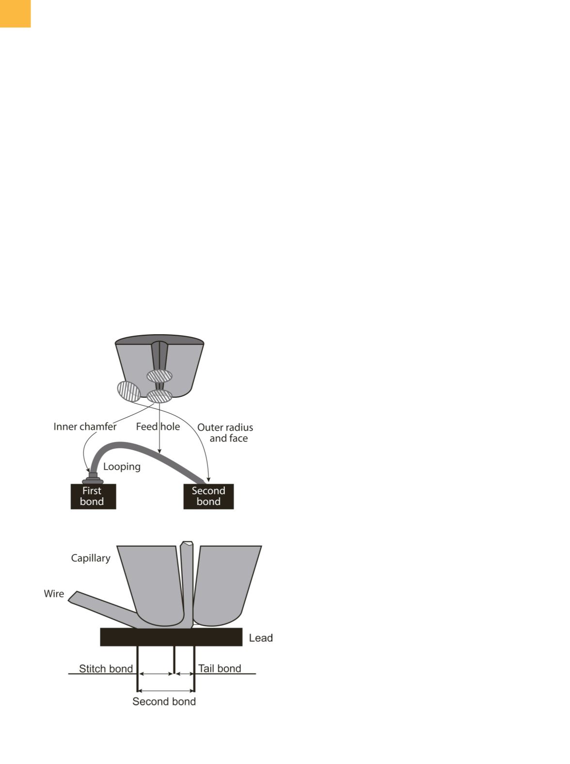
Fig. 3
Capillary tip showing features that effect portions of
the bond