


 20 / 62

ADVANCED MATERIALS & PROCESSES •
AUGUST 2014
20
the length indicates fatigue, SCC, or brittle overload.
Higher magnification optical microscopes were used
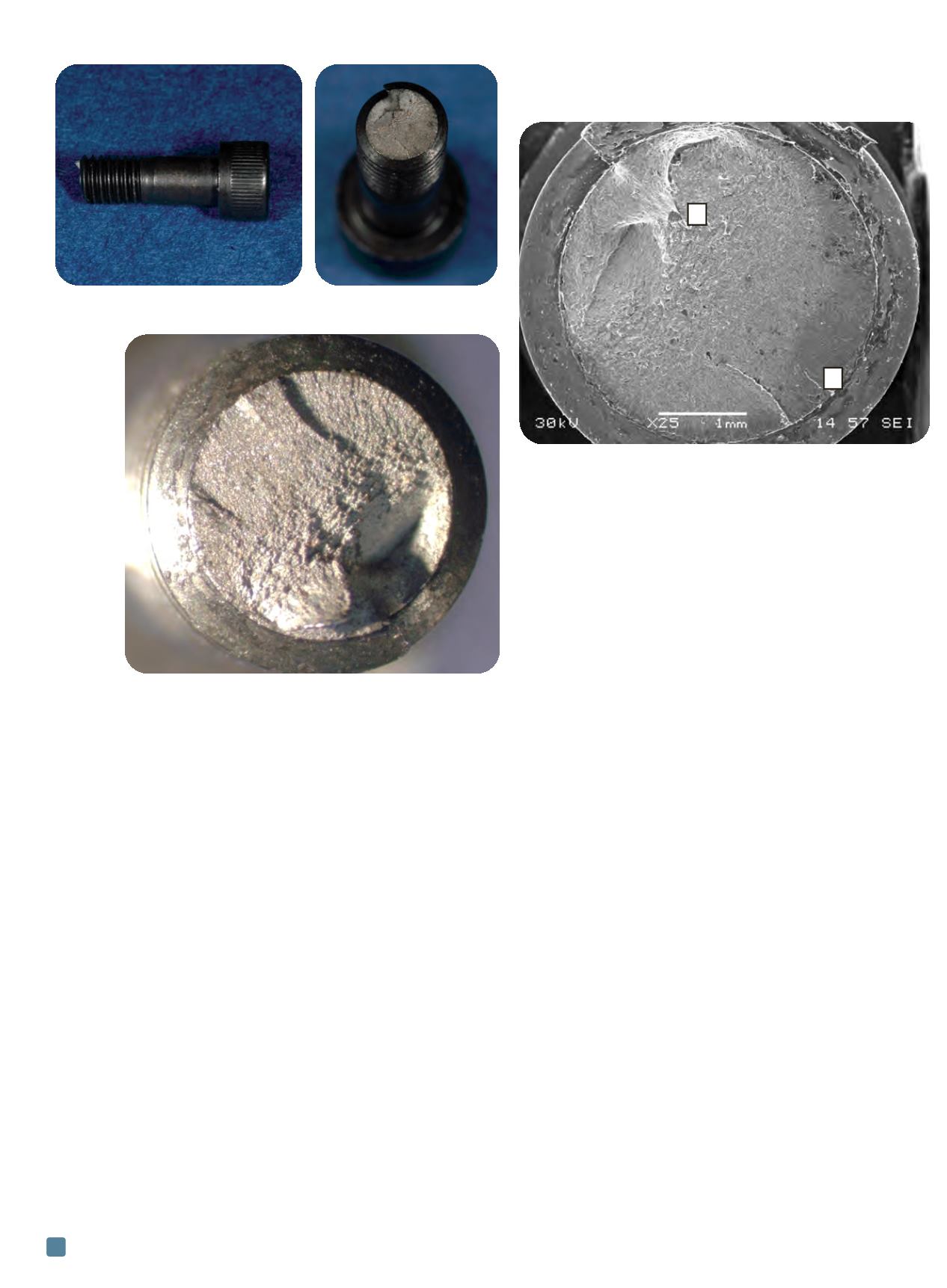
for fractography, as shown in Fig. 4. In this image, multiple
ratchet marks are visible. These marks are caused by mul-
tiple cracks that initiate on separate planes and eventually
grow together to minimize crack surface energy. Fatigue
fractures typically exhibit ratchet marks where high
stresses cause multiple crack initiation, or in areas of high
stress concentration, such as at the threaded fastener root.
Final overload fracture was observed on the side opposite
the fracture origin. Beachmarks were also observed as in-
dicated in Fig. 4. These are typically concentric bands that
radiate from a crack origin(s), are formed by the advance-
ment of a crack front as it travels through the part, and
often indicate fatigue crack growth. Fracture surfaces asso-
ciated with other progressive cracking mechanisms, such
as SCC, can also show beachmarks in metals. However,
given the observed ratchet marks, beachmarks, and gen-
eral lack of evidence to suggest corrosion or the presence
of a corrosive environment, optical microscopy indicates
that fatigue is the most likely cause of the screw fractures.
Fractured screws were analyzed using scanning elec-
tron microscopy (SEM) to confirm fatigue crack initiation
and growth. An overall image is presented in Fig. 5, simi-
lar to the optical image in Fig. 4. Generally, the fracture
surface was relatively featureless, which is typical of fatigue
in high strength steels
[1]
. Two regions were targeted for in-
spection, an area near a crack initiation location (A) and
an area in the overload region (B) where final fracture oc-
curred. Areas of intergranular fracture were observed at
the crack origin area, as shown in Fig. 6. Intergranular frac-
ture is undesirable and consistent with embrittlement in
41xx steel. The final fracture region (Fig. 7) shows mi-
crovoid coalescence, which is expected of overload follow-
ing the stable crack propagation region.
Energy dispersive spectroscopy (EDS) was used to as-
sess material composition. While not quantitative, EDS can
provide useful information. For example, the incident
screw contained carbon, manganese, iron, and chromium.
Nickel was not detected. The lack of observed nickel and
the listed ASTM A 574 specification suggest that the
screws were likely 41xx-series alloys. Microhardness meas-
ured at 419 HV, which correlates to approximately 43 HRC
and a tensile strength of roughly 200 ksi. These values are
on the high end of the product specification, which is up to
43 HRC and 180 ksi tensile strength.
SEM-based fractographic analysis shows that incident
screws suffered from small areas of intergranular fracture
at the initiation sites. Embrittlement-based intergranular
fracture in these screws could have been caused by hydro-
gen embrittlement, tempered martensite embrittlement
(TME), or reversible temper embrittlement (RTE). Any of
these forms of embrittlement can reduce fatigue perform-
ance of quenched and tempered steels. Given the screw
hardness values and that only a limited fracture area ex-
hibits intergranular fracture, TME is the most likely cause
of the small intergranular initiation areas. TME can occur
when tempering a susceptible steel for relatively short
times (one hour) in the 260°-370°C temperature range
[9]
.
Fig. 3 —
Photographs show a relatively flat fracture surface in relation to
screw length.
Fig. 4 —
Stereoscope optical image of the screw’s fracture
surface, showing signs of fatigue. Ratchet marks are visible
between the 9 and 12 o’clock positions, while the final overload
region occurs roughly at the 5 o’clock position.
Fig. 5 —
SEM image of the fracture surface showing the
ratchet mark(s) located at the 5 o’clock position and the final
fracture region at the 11 o’clock position. These two regions
have been labeled “A” and “B” respectively, and are shown at
higher magnification in subsequent figures.
B
A