


 19 / 62

joint (Fig. 1c)
[3]
. As indicated, loading on the bolt is mini-
mal until the working load exceeds preload. Thus, for a
condition where cyclic loads are smaller than preload, lit-
tle or no cyclic damage occurs to the fastener. The concept
of higher preloads resulting in increased fatigue perform-
ance may be counterintuitive, which might otherwise sug-
gest that increasing the tightening force of a bolt may
increase propensity for failure. Insufficient preload has
been attributed to the cause of the majority of fastener fa-
tigue failures
[4]
. Therefore, understanding preload is criti-
cal in both the design and failure analysis of fasteners.
Pretension is often adjusted by applying torque to the
bolt, screw, or nut. Torque application increases tension in
the fastener and clamping force between components. It is
necessary to understand the difference between clamping
force and the amount of torque applied to the screw or
bolt. These two metrics generally correlate, but are differ-
entiated by frictional forces. Fatigue susceptibility can be
reduced by increasing clamping force and fastener tension,
which is most often controlled by applied torque. However,
factors such as material hardness and surface finish affect
friction
[3]
, and therefore affect the extent to which applied
torque is translated into increased fastener tension and
clamping force.
Guidance is provided with respect to the degree to
which fasteners should be tightened. Bolts in tension
should exert as much force on the joint as it and the joint
members will stand
[4]
. A rule of thumb is to load the bolt to
60% of the material’s yield strength
[5]
.
While tension and high clamping force are critical for
joints, applied forces (often cyclic) can significantly reduce
preload. Generally, increased preload reduces the propen-
sity for fastener loosening. To minimize susceptibility to
loosening, the highest preloads possible should be used—
up to, but not exceeding yield
[4]
. Loosening reduces pre-
load and the force required for joint separation, and can
greatly increase the propensity for fatigue failure and fret-
ting. However, increasing the preload also increases sus-
ceptibility to overload upon installation, or may increase
susceptibility to SCC.
Excessive preloads can also increase mean stress to lev-
els that may contribute to fatigue for joints subjected to rel-
atively low cyclic stress amplitudes. The effect of increased
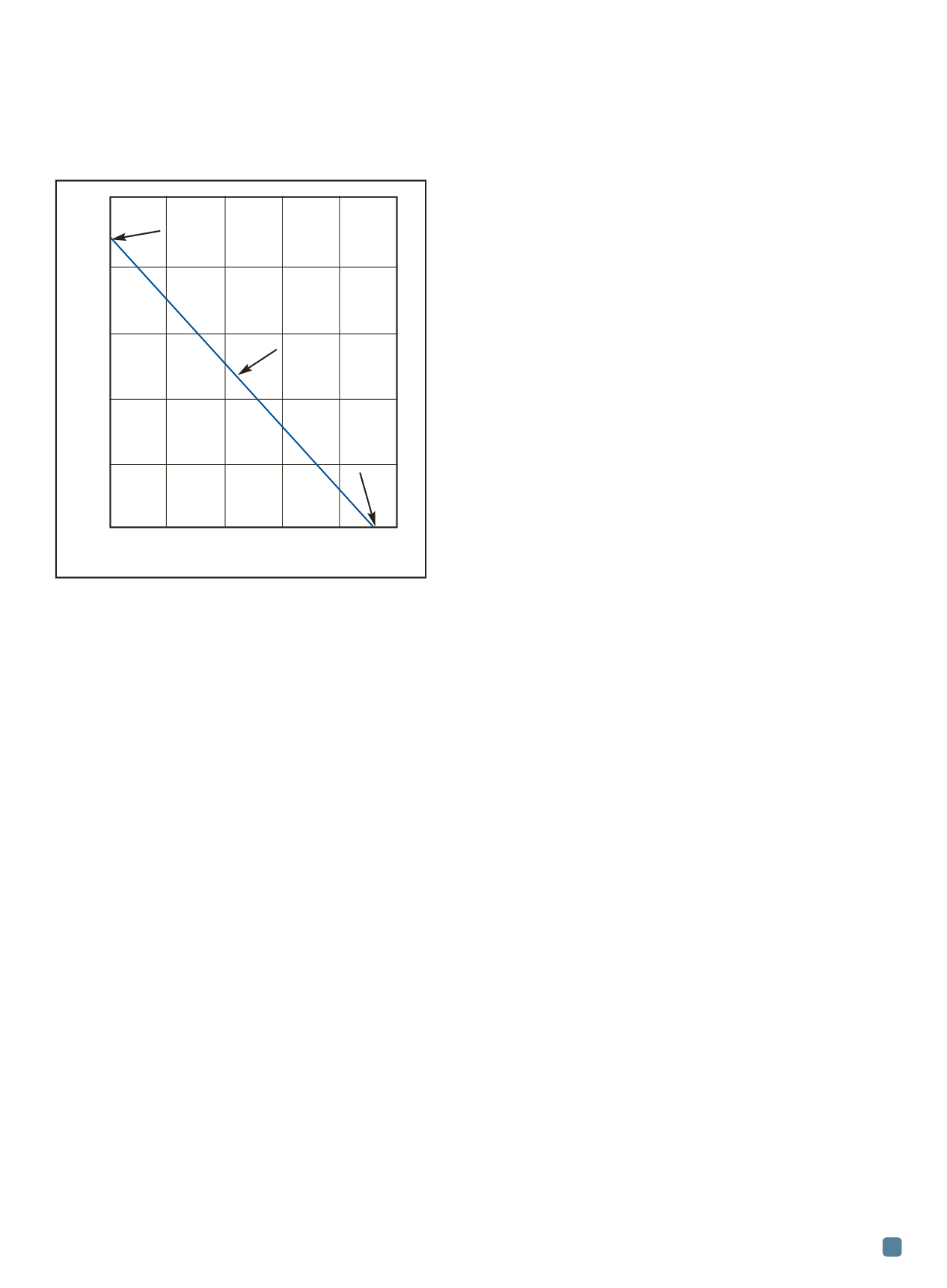
mean stress on fatigue performance is often described by a
Goodman line, which plots stress amplitude as a function
of mean stress. A schematic Goodman line is shown in
Fig. 2, where increasing mean stress results in decreased
ability for the component to withstand applied alternating
stress. As shown by the Goodman line, excessive mean
stresses (near the fastener tensile stress) can reduce fatigue
performance. However, in most joints, high preloads pre-
clude significant cyclic stresses, as shown in Fig. 1.
Hex-head case study
A short case study highlights some common issues ob-
served in fastener failures. In this example, multiple broken
steel hex-head screws were submitted for failure analysis.
These screws had been part of equipment used in a silicon
wafer fabrication system. The screw service environment
was in a cleanroom, with exposure to no known corrosive
media. In addition to the failed screws, material specifica-
tions, drawings, and installation instructions and specifica-
tions were provided. Representative images from some of
the screws are presented here.
Laboratory analysis
Through the course of the investigation, it was estab-
lished that the screws in question were installed with a tor-
sional specification of 50 in.-lb. During service, screws
were subjected to cyclic bending loads. Screws had the fol-
lowing specifications:
• UNRF 10-32 thread-form
• 38-43 HRC
• Minimum yield and tensile strengths of 162 and
180 ksi
• Max recommended load: 3150 lb
• Recommended torque setting: 79 in.-lb
• Material composition in accordance with ASTM
A 574 specifies 10 different steel alloys, the majority
of which are 41xx-series steels.
Screws were analyzed to look for macroscopic indica-
tions of failure mode. As shown in Fig. 3, fracture occurred
in the threaded region. The fracture plane was generally
perpendicular to the screw length, with no significant plas-
tic deformation. Given that the screws were known to be
loaded in tension and bending, fracture perpendicular to
ADVANCED MATERIALS & PROCESSES •
AUGUST 2014
19
Fig. 2 —
Schematic plot shows the typical relationship between
alternating and mean stress.
0 20 40 60 80 100
Mean stress, ksi
50
40
30
20
10
0
Stress amplitude, ksi
Fatigue limit
or fatigue strength
Synthetic Haigh diagram
with Goodman line
Goodman line
Ultimate
strength
Alloy steel 90 ksi ultimate
tensile strength
Goodman line
represents uncorrected
10
6
estimate
at 50% failure
Criterion: Separation