


 23 / 54

A D V A N C E D
M A T E R I A L S
&
P R O C E S S E S | J A N U A R Y
2 0 1 7
2 3
The inverse pole figure color map
image in Fig. 3 shows the bainitic struc-
ture formed from a prior austenite grain
at 270°C for 7 h in 0.6 C steel. Colors
correspond to the crystallographic ori-
entation normal to the observed plane,
representing different crystallographic
variants. Black boundaries were drawn
where the misorientation angle is
greater than 10° or austenite is pres-
ent. A prior austenite grain was divided
by bainitic packets consisting of three
bainitic blocks where each block con-
tains a single variant of the bainitic lath.
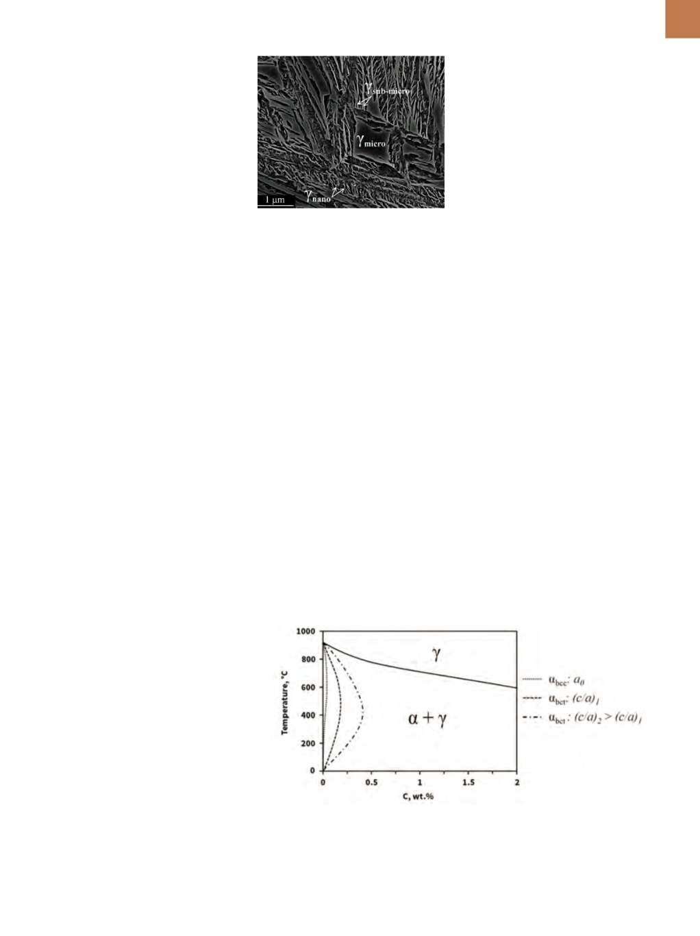
RETAINEDAUSTENITE
The nanoscale structure is not
exclusive to bainitic ferrite, as retained
austenite trapped between the plates
of ferrite also has a size <100 nm
(Fig. 2b)—so-called
nanofilms
. In low-
temperature bainitic structures, the
term
microblock
is used to denote
blocks of retained austenite >1000 nm,
while
submicron block
refers to those
between 100 and 1000 nm. Figure 4
shows the multiscale character of the
austenite in 0.6 C steel transformed at
250°C for 15 h.
Morphology and the chemical
composition are key factors controlling
the mechanical stability of austenite.
Carbon has the strongest influence on
enhancing mechanical stability
[6]
, while
at an atomic level, there is a strong cor-
relation between austenite feature size
and the amount of carbon retained in
solid solution (the smaller the size, the
higher the carbon level)
[8]
.
Transformation-induced plasticity
(TRIP) of austenite is thought to enhance
ductility if the austenite is moderately
stable against straining; for example,
when associated strain hardening ef-
fectively increases resistance to necking
and fracture. To this end, a wide distribu-
tion of sizes of retained austenite in the
microstructure (Fig. 4) leads to effective
variations of austenite stability, spreads
the transformation effect along strain-
ing, and postpones localization
[9]
.
CARBON SUPERSATURATION
IN FERRITE
Atom probe tomography shows a
high level of carbon in bainitic ferrite
without linear or surface defects, which
was over 10 times above what was
expected
[10]
. As transformation tem-
perature decreases, the carbon amount
remains high after transformation.
There are two possible explana-
tions of the abnormally high carbon
content in bainitic ferrite. The first
points toward a change in symmetry
from the conventional cubic unit cell
(bcc) into a tetragonal lattice (bct). The
second points to a high density of point
defects, particularly vacancies
[11]
.
Synchrotron radiation and x-ray
diffraction experiments show a tetrag-
onal or slightly orthorhombic unit
cell of bainitic ferrite capable of hold-
ing the excess carbon
[12]
. Likewise,
first-principles calculations prove that
when tetragonal ferrite is in para-equi-
librium with austenite, it has a much
greater solubility for carbon than is the
case for cubic ferrite under the same
conditions
[13]
. In this scenario, the ret-
rograde shape of the α/α+γ equilibrium
phase boundary in the Fe–C phase dia-
gram is displaced toward higher car-
bon solubility in ferrite providing that
tetragonality (
c/a
ratio) increases as
seen in Fig. 5.
On the other hand, specific inter-
stitial lattice sites near defects in bain-
itic ferrite provide lower-energy sites
for carbon than the regular interstitial
lattice positions, which would result
in an increased solubility of carbon in
the ferrite. Computational calculations
support this increased solubility of car-
bon in cubic iron caused the formation
of vacancy-carbon complexes
[14]
. How-
ever, further experimental evidence of
this unusually high density of vacancies
in bainitic ferrite is required.
SUMMARY
Nanostructured bainitic steels
have been theoretically designed
and manufactured using conventional
industrial practices, achieving mechan-
ical properties never recorded before in
bainite structures. Bainitic steel micro-
structures consist of extremely fine
plates of carbon-supersaturated ferrite
and retained austenite. The increased
solubility of carbon in ferritemight form
Fig. 4
—
SEM of microstructures in 0.6 C
steel obtained by isothermal transforma-
tion at 250°C for 15 h.
Fig. 5
—
Fe–C binary phase diagram considering only ferrite and austenite show the effect of
tetragonal ferrite (
α
bct
) with different c/a ratios on the
α
/
α
+
γ
equilibriumphase boundary com-
pared to cubic ferrite (
α
bcc
).