


 20 / 54

A D V A N C E D M A T E R I A L S & P R O C E S S E S | J A N U A R Y 2 0 1 7
2 0
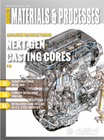
shown in Fig. 2 was built to suit the high
pressure die casting system. Molten
metal is delivered by a central runner
and fed to each cylinder through a sin-
gle gate located in the cylinder center.
The core shape, also shown in Fig. 2,
consists of two flanges beyond the cyl-
inder ends, which are designed for core
installation inside the die cavity.
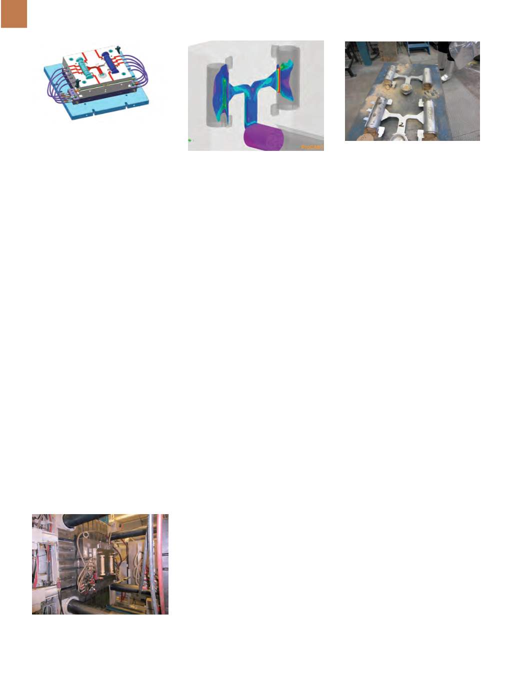
A metal flow simulation verified
die design and cavity filling conditions.
The value of metal injection velocity at
the gate, as it flows into the core, rep-
resents the essential parameter for core
design. For a plunger speed of 1 m/s,
the approximate melt velocity at the
gate will reach 15 m/s (Fig. 3).
MANUFACTURING TECHNIQUE
Cores are made of silica sand and
the binding system is a water soluble
material that can withstand casting
temperatures and be easily removed
by dissolution after casting. The binder
is mixed with the granular media at 1-5
wt%, binder to media. The mixed mate-
rial is then blown into the corebox and
dried using heated tooling and hot air.
The level of binder to granular media is
such that there remains interconnect-
ed porosity in the manufactured core.
This porosity allows the water based
solution to penetrate the core in order
to dissolve it after casting.
A shield, made of metal, ceramic,
or glass fiber, or a combination, may
be placed near the casting in-gates to
protect the core from the high velocity
impingement of metal coming from the
gates during filling. The shield may be a
bit larger than the gate area, but could
be any desirable or practical size. Gen-
erally, the shield may either be placed
in the corebox during core making or af-
fixed to the core after production.
TEST RESULTS
Performanceof experimental cores
was tested using a 1200-ton Bühler high
pressure die casting machine and com-
mercial grade aluminum alloy A356
(Fig. 4). The 800 kg load of molten
metal was held in a Stotek furnace at
710°C. A variety of core solutions were
tested with sand, surface coatings, and
shields inserted in gate areas. A variety
of casting process parameters, such as
injection speed or injection pressure,
were also tested. Casting trials show
that correctly designed cores do not
collapse during injection and allow
manufacturing of sound parts. Figure 5
shows that the essential part of the
cores remains inside components.
Once optimal core design and
structure are determined, implementa-
tion in a commercial part with a more
complex shape and varying wall thick-
ness will occur. Another series of tests
will take place at a commercial die cast-
ing facility.
SUMMARY
CanmetMATERIALS, in collabo-
ration with General Motors and other
industrial partners, worked to develop
core technology for high pressure die
casting in order to enable high volume
and low-cost manufacturing of light-
weight automotive components with
complex hollow structural shapes. Al-
though experimental verification of the
concept using a part with simplified ge-
ometry looks promising, the technique
requires further testing using commer-
cial components with internal cavities
of complex geometry.
~AM&P
For more information:
Frank Czerwinski is
senior research scientist and innovative cast-
ing group leader, CanmetMATERIALS, 183
LongwoodRd.South,Hamilton,Ontario,L8P
0A5, 905.645.0887, frank.czerwinski@can-
ada.ca
,www.canmetmaterials.nrcan.gc.ca.
Acknowledgments
The authors acknowledge the financial
support of the ecoEnergy Innovation
Initiative program of Natural Resources
Canada and General Motors, and thank
members of the Innovative Casting
Group at CanmetMATERIALS for assis-
tance during casting trials.
References
1. F. Czerwinski, M. Mir, and W. Kaspr-
zak, Application of Cores and Binders
in Metalcasting,
Int. J. Cast Met. Res.
,
Vol 28, p 129-139, 2015.
2. A. Prescenzi, Cast Body Nodes for
2016 Acura NSX, S
AE Int. J. Mater. and
Manuf
., Vol 8, p 722-730, 2015.
3. T. Flessner and C. Marr, Die Cast-
ing Using Casting Cores, U.S. Patent
5,303,761, 1994.
Fig. 2 —
CAD drawing of two-cavity die
built for high pressure die casting trials.
Fig. 3 —
Modeling of die filling during
injection shows melt velocity at different
locations within the runners and cast part.
For a plunger velocity of 1 m/s, the corre-
sponding melt velocity at the gate is 6 m/s.
Fig. 4 —
Clamp area of high pressure die
casting machine with cores installed directly
before die closing and injection of liquid alloy.
Fig. 5 —
Aluminum test components man-
ufactured using strong core technology
and high pressure die casting.