


 37 / 62

iTSSe
TSS
A D V A N C E D
M A T E R I A L S
&
P R O C E S S E S | J U L Y / A U G U S T
2 0 1 6
3 7
7
iTSSe
TSS
FEATURE
coating thickness images. However, dark field mode is pref-
erable when a more quantitative assessment of coating
pores is desired.
iTSSe
For more information:
Dheepa Srinivasan is a principal engi-
neer at GE Power, GE India Technology Center, Bangalore,
dheepa.srinivasan@ge.com,
www.ge.com.
This article series is adapted from
Chapter 5, Cold Spray—
Advanced Characterization,
in High Pressure Cold Spray—
Principles and Applications, edited by Charles M. Kay and
J. Karthikeyan (ASM, 2016).
grinding and polishing to yield a mirror finish. Because most
of the samples are made of metallic or composite materials,
mechanical abrasive cutting or electrodischarge machine
wire cutting is typically used. However, in some cases, these
have been found to result in delamination of the coating
from the substrate, and therefore, waterjet cutting is rec-
ommended in order not to impart stresses during cutting.
Typically, samples are viewed in bright field mode to obtain
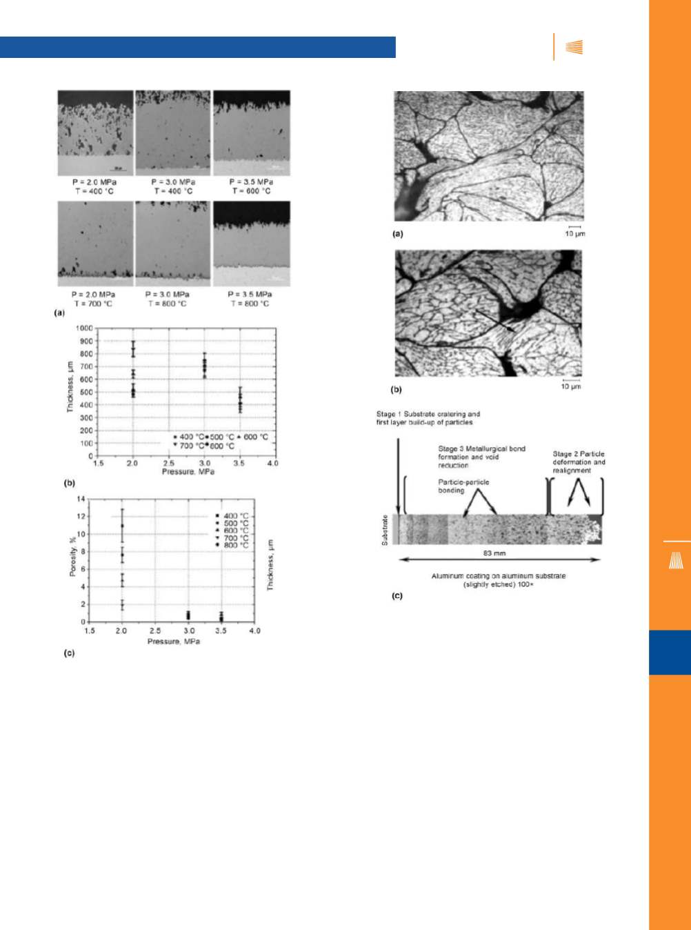
Fig. 3 —
Optical micrographs with etched aluminum coatings as a
function of gas temperature at 204°C (400°F) (a) and 315°C (600°F)
(b) reveal extent of particle deformation. Micrographs determine the
nature of the coating bond (c).
Fig. 2 —
Optical micrographs depict variation in porosity with
processing parameters for a Ti-64 coating on a SS304 substrate (a).
Variation of porosity with thickness and gas pressure as measured
from the optical micrograph (b, c).