


 18 / 86

A D V A N C E D M A T E R I A L S & P R O C E S S E S | A P R I L 2 0 1 6
1 8
Strain measurement primarily
applies when servohydraulic systems
are used for static tests. In these cases,
typically a sensor arm extensometer,
such as Zwick’s makroXtens device, will
accommodate the need for a high preci-
sion form of strain measurement. With
this extensometer, deformations on the
specimen are acquired in the elastic
and plastic deformation ranges during
the entire tensile test up to specimen
break. Tiltable knife edges avoid the
onset of damage to the specimen up to
the breaking point.
Clip-on extensometers may also
be used. As the name implies, these
devices are mounted directly onto
the specimen. The mechanical parts
that transfer extension, via knife edg-
es, from the specimen to the internal
transducer are short and stiff. Prac-
tically no relative movement occurs
between the specimen and exten-
someter, resulting in a highly accurate
measurement.
For dynamic tests, a simple clip-
on extensometer can be used as well
as an optical system such as a non-
contact video extensometer. Video
extensometers require measurement
marks to be attached to the specimen
that are optically distinct from the sur-
rounding area of the specimen. Marks
are clipped, tacked, or glued onto the
specimen, or the specimen is marked
with a colored pen.
LOW CYCLE AND HIGH
CYCLE FATIGUE TESTS
In industry, the focus of ser-
vohydraulic machines is mainly the
testing of components, though they
are indeed applicable for materials
TABLE 1
—
TESTING SYSTEMS AT-A-GLANCE
Type of system Load range Frequency
range
Mode of operation
Electromechanical
0.5 to 2500 kN Up to 1 Hz
Primarily static
Servohydraulic
5 to 2500 kN Up to 100 Hz
Both static and dynamic
Vibrophore high-
frequency pulsator
50 to 1000 kN 30 to 300 Hz
Both static and dynamic
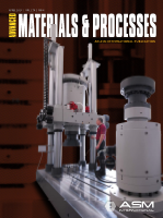
The HB100 servohydraulic testing ma-
chine has a load range of up to 100 kN.
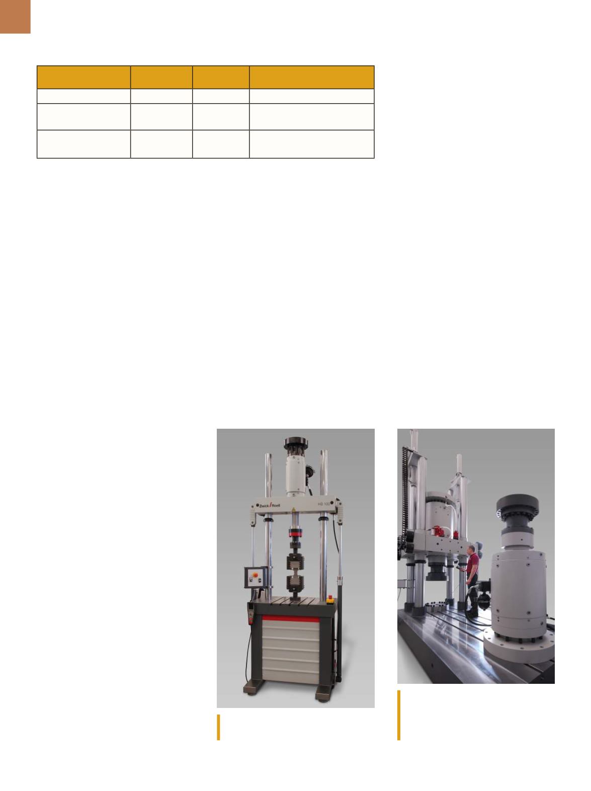
The HB3500 servohydraulic testing
machine is applicable for testing large
components used in construction
applications.
characterization as well. Applications
typically call for a form of fatigue test-
ing to support lifecycle determination.
Fatigue testing involves subjecting a
component or specimen to cyclic load-
ing. Two common types of fatigue test-
ing are regularly investigated with ser-
vo hydraulic systems—low cycle fatigue
(LCF) and high cycle fatigue (HCF).
Components that are subject to
extreme thermal and mechanical forc-
es can only be designed in the range
of short-term strength, that is, up to a
maximum of 105 cycles. Prime exam-
ples include the turbine blades and
discs used in aircraft engines, together
with stationary turbines for power gen-
eration, plus items such as exhaust gas
turbochargers, exhaust manifolds, and
other similar components.
In these components, strain-
induced plastic cyclic deformation oc-
curs at designed-in notches such as the
blade-disc joint. Sooner or later this re-
sults in crack nucleation. In a low-cycle
fatigue (LCF) test, these forces or strains
are simulated on a specimen and the
number of cycles to crack initiation is
determined. The elastic field around
the crack also has a supporting effect
after crack initiation. Further crack
growth then occurs in accordance with
fracture mechanics criteria. Results are
used directly in the calculation of the
anticipated service life. Tests are per-
formed at constant amplitude and hold
times can additionally be interspersed
to investigate creep or relaxation pro-
cesses. A triangular waveform is used
as a set value, or a trapezoidal wave for
hold times.
If specific operating loads are to be
simulated, other strain-time sequences
are also possible. Thus LCF tests are
also performed with a superimposed
higher-frequency oscillation. The test