


 19 / 86

A D V A N C E D
M A T E R I A L S
&
P R O C E S S E S |
A P R I L
2 0 1 6
1 9
frequency is usually lower than or equal
to 1 Hz, although this limit is constantly
shifting upward with the result that LCF
tests are regularly performed at up to
10 Hz. Strain control is used for these
tests. Only in special cases is there a
change to force-control in the stabi-
lized hysteresis region or for hold times
in order to investigate creep effects.
Tests for materials characterization are
usually performed with an R ratio of -1.
Historically, most attention has focused
on situations that require more than 10
4
cycles to failure where stress is low and
deformation is primarily elastic.
High-cycle fatigue (HCF) refers
to the effect of low-amplitude, high-
frequency vibration within the elastic
strain region for a number of load cy-
cles N, where typically N > 10
5
. High-
cycle fatigue tests typically occur over
10
7
cycles with some materials re-
quiring up to 5 × 10
8
cycles. While the
applied stress is within the material’s
elastic region, plastic deformation can
still take place on a microscopic level
as the part ages, eventually leading to
component failure. A component or
material’s fatigue characteristics can
be quantified by generating the graph
of stress versus cycles at a given load,
known as the Wöhler curve, where fa-
tigue strength is determined from the
maximum stress the specimen or com-
ponent can withstand for a specified
number of cycles. The endurance limit
of the material or part is then defined
as the stress level below which failure
does not occur, meaning it has theoret-
ically infinite life. Because fatigue fail-
ures can occur quickly if the endurance
limit is exceeded, performance must
be guaranteed by demonstrating ad-
equate fatigue strengths through cy-
clical testing that simulates installed
conditions.
S-N curves are derived from tests
on samples of the material to be char-
acterized, often called coupons, where
a regular sinusoidal stress is applied
by a testing machine, which also
counts the number of cycles to failure.
This process is sometimes known as
coupon testing. Each coupon test gen-
erates a point on the plot, although in
some cases there is a run-out where
the time to failure exceeds that avail-
able for the test. The progression of
the S-N curve can be influenced by
many factors such as corrosion, tem-
perature, residual stresses, and the
presence of notches.
Analysis of fatigue data requires
techniques from statistics, especially
survival analysis and linear regression.
The Goodman relation, an equation
used to quantify the interaction of
mean and alternating stresses on the
fatigue life of a material, lends support
for fatigue data analysis. The general
trend presented by the Goodman re-
lation is one of decreasing fatigue life
with increasing mean stress for a given
level of alternating stress. A Goodman
diagram is a graph of mean stress ver-
sus alternating stress, demonstrating
when the material fails at a given num-
ber of cycles.
VIBROPHORES FOR HIGH
CYCLE FATIGUE TESTING
Magnetic resonance testing ma-
chines, also known as high-frequency
pulsators or Vibrophores, are advanced
systems for HCF testing. Zwick Vibro-
phores are specifically designed for
rigid metal or ceramic specimens and
can induce low-amplitude stress cycles
at loads similar to those experienced in
aircraft applications.
Operating at high test frequencies,
Vibrophores can perform a fatigue test
in a short period of time, enabling in-
creased specimen throughput. For ex-
ample, a Vibrophore requires 20-40%
of the time a servohydraulic machine
requires to run the same number of
cycles. This fast testing capability is
essential in a production environment
where several specimens from each lot
must be successfully tested before the
lot can be released for use.
The Vibrophore functions like a
driven oscillator, where a large mass
on the end of a spring is subjected to
an external, time-dependent force.
When installed in the testing machine,
the specimen functions as the spring,
and is oscillated by the excitation mass
via the resonance drive. The greatest
force amplification occurs when the
oscillation amplitude matches the
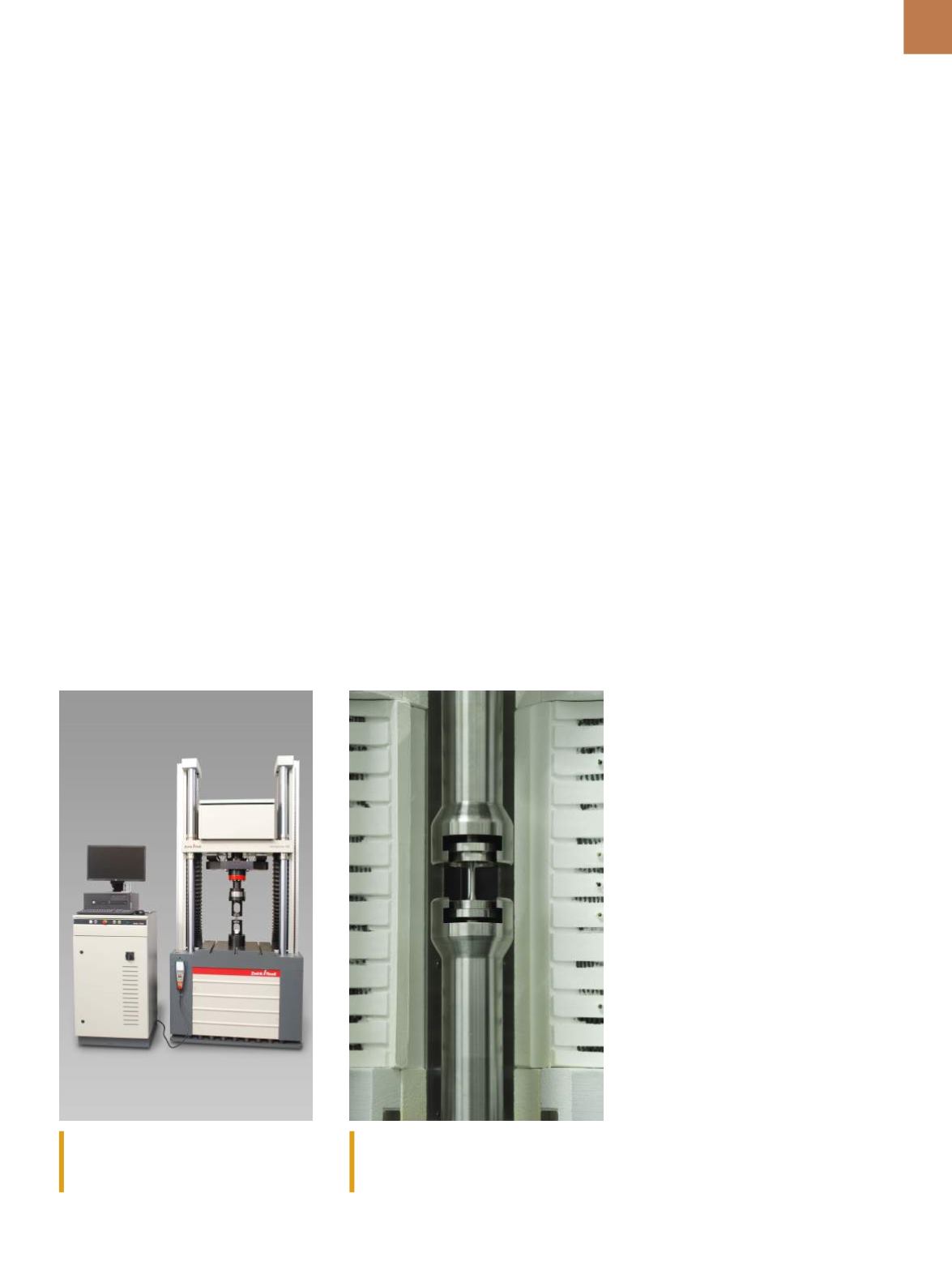
The remote-controlled Vibrophore 100
systemprovides ergonomic testing in a
compact footprint.
The wide test area of this Vibrophore
system accommodates HCF testing at
non-ambient temperatures.