


 32 / 102

A D V A N C E D M A T E R I A L S & P R O C E S S E S | O C T O B E R 2 0 1 5
3 2
CASE STUDY
FAILURE ANALYSISOF
A FRACTURED PIN
A pin used to hold the side plates together in a conveyor chain system
fractured and failed, prompting a metallurgical failure analysis.
A
pin that was used as part of a
conveyor chain application failed
in service. The company want-
ed to find out what went wrong, so they
submitted the fractured pin to a failure
analysis laboratory for metallurgical
inspection. Loading applied to the pin
was expected to be shear in nature, and
perpendicular to the 59-mm-diameter
surface at the ends of the pin. Specifical-
ly, the owner of the failed pin wanted to
determine if inclusions may have caused
the failure, if the part had been properly
heat treated, andwhether or not the steel
composition was correct.
VISUAL INSPECTION AND
SEM-EDS ANALYSIS
Both visual inspection and scan-
ning electron microscopy/energy dis-
persive x-ray spectroscopy (SEM-EDS)
were initially used to study the failed
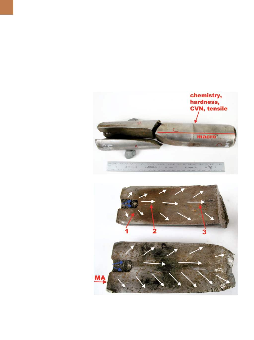
pin (Fig. 1). Longitudinal fracture surfac-
es are shown in Fig. 2, with blue arrows
indicating the fracture origin region and
white arrows indicating the cracking
direction. Section MA was selected for
metallography and locations 1 through
3 were chosen for closer inspection.
A magnified view of location 1 is
shown in Fig. 3, which also exhibits sub-
stantial post-fracture rubbing damage.
A scanning electron micrograph of lo-
cation 1 is presented in Fig. 4, although
the rubbing damage obscures the origi-
nal fracture features. Verification of the
fracture mode could not be established
due to the rubbing damage.
A deposit at location 2 was ana-
lyzed using EDS, which detected a trace
amount of chlorine in addition to a few
other foreign elements. Chlorides are
known to be corrosive to stainless steel
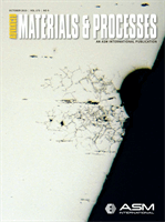
Fig. 1 —
Remnants of the failed pin are shown with sections identified as A through C.
Fig. 2 —
Fractures on sections A and B are shown with section MA selected for metallog-
raphy. Locations 1 through 3 were selected for closer inspection. Blue arrows indicate the
fracture origin region while white arrows show the direction of cracking.
and can contribute to stress-corrosion
cracking (SCC). Threads from the hole at
the origin region are shown in Fig. 5 and
corrosionpits canbe seenon the threads.