


 33 / 102

A D V A N C E D
M A T E R I A L S
&
P R O C E S S E S |
O C T O B E R
2 0 1 5
3 3
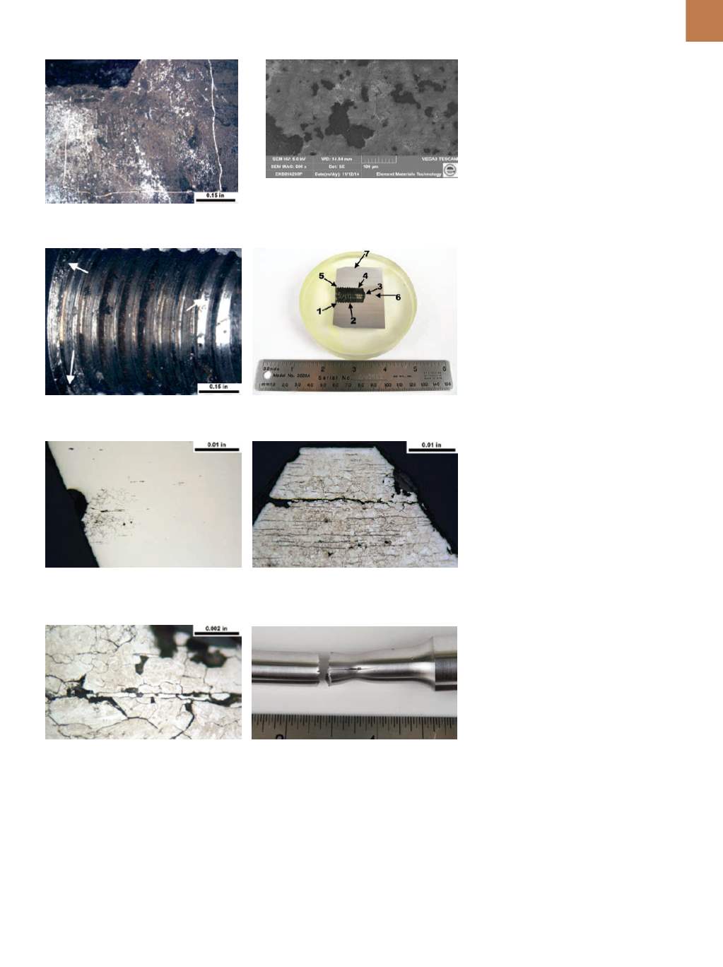
Fig. 5 —
Magnified view of pin threads.
Arrows indicate corrosion pits.
Fig. 6 —
Section MA includes locations 1
through 7, which were closely examined.
Fig. 7 —
Magnified view of location 3. A pat-
tern of branched cracks is present adjacent to
a corrosion pit.
Fig. 8 —
Magnified view of a thread crest at
location 2. Microstructure consists of martensite
and semi-continuous stringers of delta ferrite.
Fig. 9 —
Higher magnification view of right
center of Fig. 8. Cracking progressed along
grain boundaries and delta ferrite stringers.
Fig. 10 —
Fractured tensile specimen exhibits a
longitudinal crack on the bar.
TENSILE TEST RESULTS
The ultimate strength of the ten-
sile specimen was 1200 N/mm
2
and
exceeded the maximum requirement
of 1050 N/mm
2
. The fracture on the
tensile specimen is shown in Fig. 10,
which exhibits a longitudinal crack on
one half of the specimen that partial-
ly split the piece. Splitting was caused
by the semi-continuous delta ferrite
stringers, which indicates that the ma-
terial was brittle in the pin’s longitudi-
nal direction.
CHARPY V-NOTCH
IMPACT TESTING
Charpy V-notch specimens were
excised from the pin with the notches
oriented longitudinally. The result for
each test was 2 Joules, which did not
meet the requirement of 25 Joules.
Longitudinal features were present on
the fracture surfaces that were asso-
ciated with delta ferrite stringers. This
low impact strength was caused by the
semi-continuous delta ferrite stringers.
CONCLUSIONS
Pin cracking initiated at the
threaded hole where there was corro-
sion pitting and evidence of SCC. The
cracking is thought to have progressed
via corrosion fatigue or brittle overload
fracture. The microstructure of the pin
consisted of semi-continuous delta fer-
rite stringers in a matrix of martensite.
These stringers were found to be a ma-
jor factor contributing to the pin failure.
The Charpy V-notch impact resistance
of the steel was far below the specified
requirement. Semi-continuous delta
ferrite stringers made the pin’s impact
resistance very low. Splitting of the ten-
sile specimen was due to the presence
of semi-continuous delta ferrite string-
ers and indicates that the material was
susceptible to longitudinal cracking un-
der the application of stress.
~AM&P
Formore information:
Craig Schroeder
is senior engineer, metallurgy, Element
Materials Technology, 3200 South 166th
St., New Berlin, WI 53151, 262.901.0534,
craig.schroeder@element.com,www. element.com
.
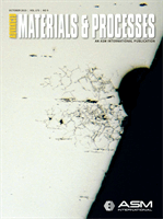
Fig. 3 —
Magnified view of location 1, indi-
cated by scribe marks.
Fig. 4 —
Scanning electron micrograph of
location 1. Post-fracture mechanical rubbing
damage obscures fracture features.
METALLOGRAPHY FEATURES
Section MA is presented in Fig. 6,
in which locations 1 through 7 were ex-
amined. A magnified view of location 3
is shown in Fig. 7, which exhibits a pat-
tern of branched cracking, indicative of
SCC. Magnified views of location 2 are
presented in Figs. 8 and 9. The micro-
structure was found to consist of mar-
tensite and semi-continuous stringers
of delta ferrite, with much of the crack-
ing through the tooth occurring along
the stringers. The presence of these
semi-continuous stringers was deter-
mined to be a major contributing factor
to the pin failure.