


 23 / 50

A D V A N C E D
M A T E R I A L S
&
P R O C E S S E S |
A P R I L
2 0 1 5
2 3
applications, and can also perform ad-
vanced applications such as strain con-
trol and dynamic testing.
Flexibility of applications:
One of
the most beneficial features of non-
contacting extensometry is its ability
to be used for almost any application.
This flexibility allows adaptation to var-
ious tests with minimal changes to base
equipment. Equally, non-contacting ex-
tensometers work well in quality con-
trol environments where repeatability
and robustness are key.
Various lenses:
Most video and la-
ser extensometers have interchange-
able lenses. The different lenses dictate
the field of view of the strain measure-
ment—how much of the test space can
be seen by the camera. Smaller field-
of-view lenses are typically used when
very high-accuracy measurements are
required, such as inmetals and compos-
ites tests, whereas larger field-of-view
lenses are used for high-elongation
tests, such as films and elastomers.
Ease of use:
Many commercially
available non-contacting extensometers
require minimal operator intervention
during the test, as they are usually inte-
grated into the test method automatical-
ly. Operators only need tomarkmaterials
with dots, lines, speckle, or other surface
patterns to be picked up by the camera.
Temperature chamber use:
Because
non-contacting extensometers do not
contact specimens, they are suitable for
both high and low temperature testing.
They can be attached to chambers that
are fitted with windows, with minimal
compromise to strain signal accuracy.
Robustness:
There are no moving
parts on most non-contacting exten-
someters, so there is little wear and
tear on the device itself. Robust devices
need less servicing over their lifetime
and can last for many years before be-
ing repaired or replaced, maximizing
the uptime of testing operations.
LOOKING FORWARD
Non-contacting strain devices are
not limited to simple elongation and
deformation measurements. Recently,
video extensometers have been used to
collect images for digital image correla-
tion (DIC). DIC is an optical technique
that has been used within research
environments for more than 30 years
and allows strain to be measured over
the entire surface of a specimen or com-
ponent. Sequential images are taken
during a test and DIC software analyzes
these post-test to extrapolate displace-
ment data by tracking changes to a
pattern either applied to the specimen
or occurring naturally in the material.
This allows a strain map, similar to an
FEA-analysis or thermal image, to be
shown for the entire surface with single
camera systems working in 2D and two
camera, or stereo, systems allowing
measurements in 3D.
As DIC provides operators with
strain data across the full field of the
specimen surface, as opposed to only
elongation between two points from
a traditional extensometer, it can also
provide more information such as
discontinuous yielding, shear strain,
localized necking, and can locate strain
hot spots. This allows FEA models to be
validated with real products and weak-
nesses in design and common failure
points to be discovered. DIC also en-
ables strains to be found that an exten-
someter would not be able to discover,
and is a valuable teaching tool as well.
Although DIC has been a popular
standalone research technique for years,
it was only recently that its capabilities
have been integrated with commercially
available video extensometers with a sim-
plified user interface, making this power-
ful analytical tool available for any capa-
blematerials testing operator.
~AM&P
For more information:
Elena Mangano
is market development specialist, In-
stron, 825 University Ave., Norwood, MA
02062, 800.877.6674,
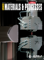
elena_mangano@ instron.com.Fig. 3 —
Digital image correlation analysis shows localized strain on a metal tensile specimen.
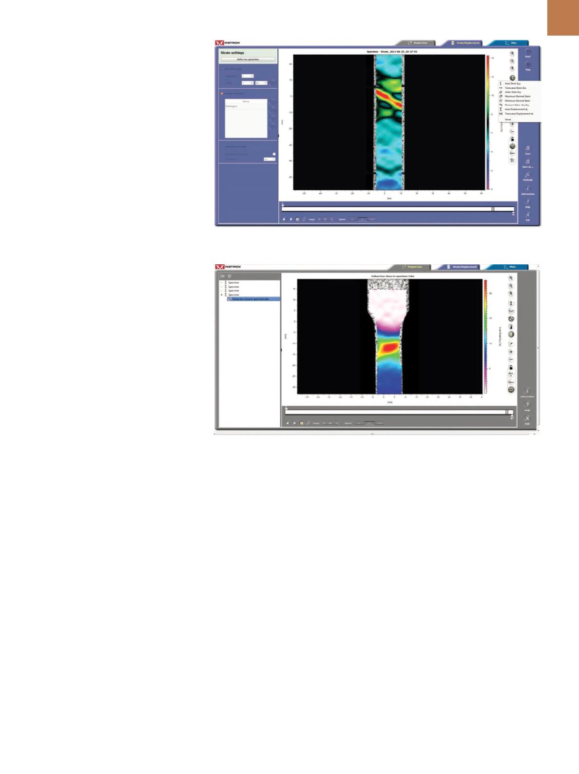
Fig. 4 —
Digital image correlation analysis shows localized strain on a plastic tensile specimen.