


 42 / 78

ADVANCED MATERIALS & PROCESSES •
NOVEMBER-DECEMBER 2014
42
HTPRO
8
dual-phase FeB-Fe
2
B layers earlier in the
cycle at shallower boride layer depths.
For example, 1018 plain carbon steel can
be boronized to about 0.004 in. deep
using commercially available Ekabor 1
boriding powders before any FeB begins
to form. A higher alloy 4140 steel can
only be borided to about 0.003 in. deep
before FeB begins to form using the same
boriding agent. Materials having even
higher alloy content, such as Types 304,
440, and 17-4 stainless steels, form FeB at
depths less than 0.001 in. Thus, plain car-
bon steels are attractive candidate mate-
rials for boriding, as they can be borided
deeper while still maintaining a single
phase Fe
2
B layer. They also are less ex-
pensive than higher alloy steels.
Dual-phase boride layers are undesirable
compared with an F
2
B single-phase layer.
The main problem with dual phase lay-
ers is that their coefficients of thermal ex-
pansion and densities differ with respect
to one another. The boride layers are
formed at relatively high temperatures
(1550°–1750°F) and these layers contract
at different rates when cooled to ambient
temperature, generating stresses between
them. The Fe
2
B layer on the steel sub-
strate is in a state of com-
pressive residual stress
(desirable) and the FeB
layer on the surface of the
Fe
2
B layer is in a state of
tensile stress. This can
cause cracks to form be-
tween the layers, and the
FeB layer often spalls off
the surface during cooling.
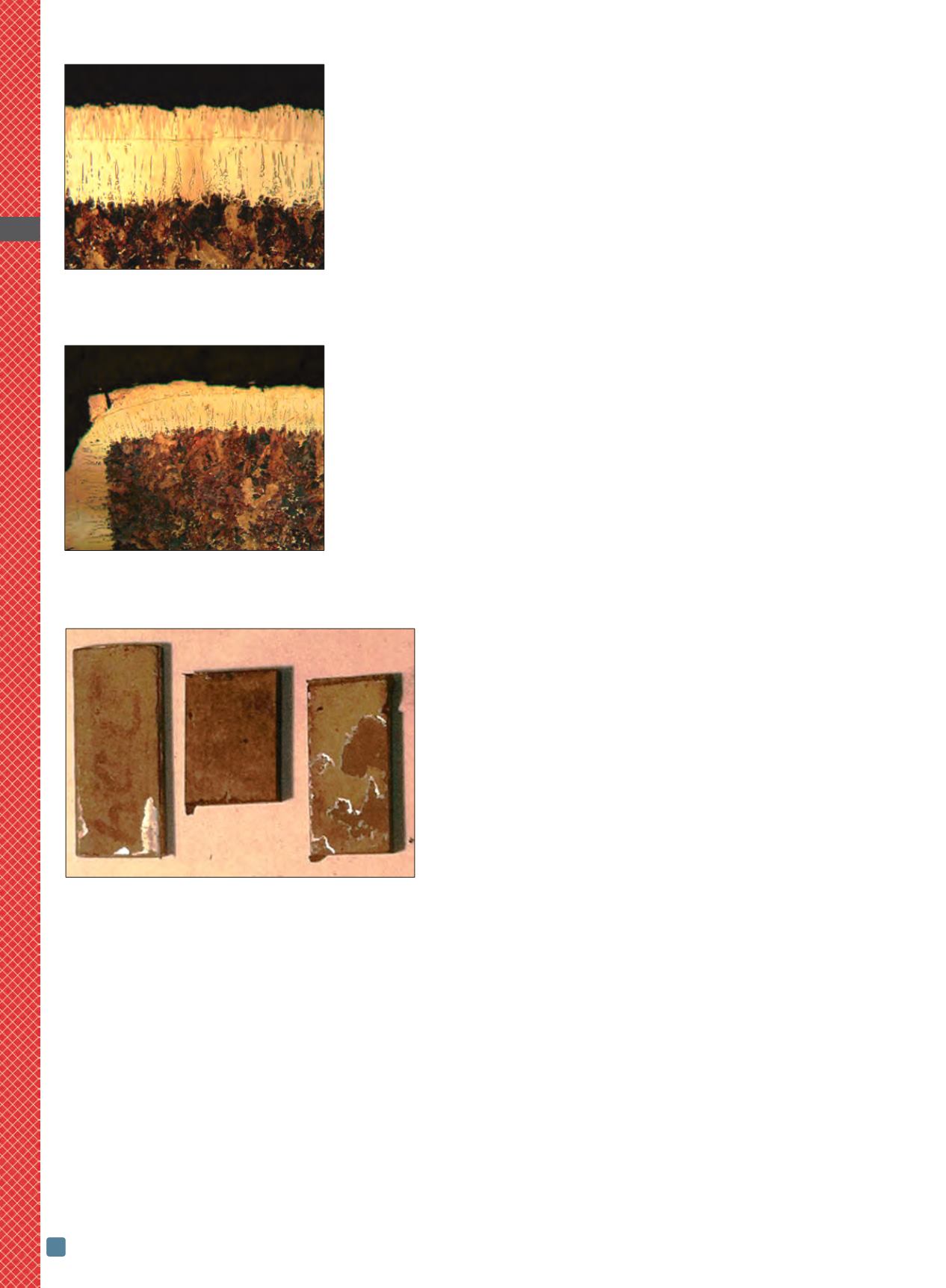
Figure 1 shows a dual-
phase boride layer consist-
ing of Fe
2
B (lighter colored
deep “teeth”) and FeB
(darker colored shallow teeth) near the
surface. Stress-related cracks in the dual-
phase layer run parallel to the material’s
surface. Cracking is even more prevalent
in borided parts having outside corners
and edges where surface boron concen-
tration is high due to simultaneous boron
diffusion into the surface from multiple
angles. Figure 2 shows an example of
spalling at the corner of a borided part
where cracks formed between the FeB
and Fe
2
B layers, resulting in the FeB layer
spalling off at the corner. If spalling does
not occur immediately during cooling,
residual tensile stresses in the FeB layer
make it very easy to chip and break dur-
ing handling and in the field. Spalled
areas appear as small silver-colored re-
flective spots (Fig. 3).
Deep case boriding
Historically, information on boriding in
the literature states that boriding deeper
than 0.005 in. is not recommended on
many materials due to dual-layer forma-
tion, which is prone to spalling and frac-
ture of the layer. However, many design
engineers want to form deeper boride lay-
ers to provide longer wear life. Recogniz-
ing this need, Bluewater Thermal
Solutions developed new deep-case borid-
ing processes for several different material
grades. While the use of high tempera-
tures and longer cycle times enables this,
the challenge is to create deeper layers
while maintaining a single-phase Fe
2
B
layer. Figure 4 shows an example of
borided 4140 alloy steel using standard
commercially available boriding powders
to a layer depth of 0.020 in. Nearly one half
of the total boride layer depth is FeB,
which is not a desirable structure.
Deep boriding with a single-phase Fe
2
B
layer in concept is simply to prevent boron
concentration at the surface from rising to
a level where FeB begins to form while al-
lowing boron to continue to diffuse
deeper. However, the powder pack process
makes this difficult due to a fixed boron
activity level. There are a number of alter-
native approaches to accomplish deep
boriding with a single-phase Fe
2
B layer:
(1). The boriding process can be carried
out at a high boron potential, then cool the
parts to ambient temperature, remove
them from the powder pack, and reheat in
a protective inert atmosphere with no
boron present to allow further boron dif-
fusion, while reducing the surface boron
concentration. A limitation of this ap-
proach is spalling of the boride layer dur-
ing cooling. In many cases, boride layers
spall off part surfaces immediately as they
are removed from the boriding process. It
is also difficult to predict what post-borid-
ing diffusion cycles are necessary to re-
duce surface boron concentrations to a
level where all the FeB borides are dis-
solved and reduced back into a single-
phase Fe
2
B boride layer.
Figure 5 shows an example of deep-case
borided 4140 alloy steel with FeB pres-
ent at the surface after boriding. The
material was reheated in an inert at-
mosphere to diffuse away FeB that
Fig. 1 —
Dual-phase boride layer with FeB
(darker “teeth” near surface) and Fe
2
B
(lighter teeth). Cracks have formed between
the FeB and Fe
2
B layers upon cooling.
Fig. 2 —
Dual-phase boride layer with
cracks between the FeB and Fe
2
B layers.
The FeB boride layer at the corner spalled
off the surface.
Fig. 3 —
Spalling (small silver-colored
relective spots) on three different materials
that were borided together: (left) 304
stainless steel, (center) 440C stainless steel,
and (right) duplex stainless steel.