


 47 / 78

ADVANCED MATERIALS & PROCESSES •
NOVEMBER-DECEMBER 2014
47
HTPRO
13
of induction coils serves as a guide in determining potential
root cause(s) of premature coil failures.
Special applications of electromagnetic induction, including
melting of glasses and oxides, optical fiber drawing, nanoparti-
cle heating, and hyperthermia applications are also discussed.
Design principles and operation specifics of modern tran-
sistor and thyristor power supplies used for induction
heating are described using conventional and advanced cir-
cuits. An appreciable amount of material is devoted to
practical aspects, including review of transformer designs
and load-matching facets and standard and customized in-
duction equipment.
Volume 4C also contains numerous case studies that illustrate
the challenges and solutions in obtaining required thermal con-
ditions for a workpiece, as well as the subtleties of computer
modeling of induction thermal processes.
Special attention is given to describing the aspects of process
monitoring, maintenance, and water cooling, as well as safety
procedures, energy efficiency, and environmental factors in-
cluding control of electromagnetic field (EMF) exposure.
EMF is invisible and is associated with the operation of any
electrical device. Several international organizations raised
concerns related to external EMF exposure, developing
awareness regarding nonionizing radiation, and the evalua-
tion of health risks associated with EMF exposure. These or-
ganizations include:
• The World Health Organization (WHO)
• The Institute of Electrical and Electronic Engineers (IEEE)
• The U.S. Occupational Safety & Health Administration
(OSHA)
• The International Radiation Protection Association (IRPA)
Studies were conducted to evaluate direct and indirect ef-
fects of EMF exposure on health, passive and active med-
ical implants, hypersensitivity, etc., leading to the creation
of a number of international standards, guidelines, and
regulations. Being unaware of basic principles related to
electromagnetic field exposure and unfamiliar with the re-
sults of studies conducted by various professional societies
and international health organizations can result in incor-
rect assumptions. One article in this handbook aims to clar-
ify this subject by reviewing key concepts regarding
occupational exposure to electromagnetic fields encoun-
tered in industrial activities with which professionals should
be aware, measures used to evaluate these situations, and
rules and international standards applicable to a 50 Hz to 10
MHz frequency range
[3]
.
Summary
This reference provides practitioners, students, engineers,
and scientists with the knowledge to better understand the
various interrelated physical phenomena of induction heat-
ing and heat treating. Much of the content in the 62 articles
in this handbook has not been published before. To provide
a snapshot of the wealth of information contained in Vol 4C,
a series of brief articles highlighting some of material in dif-
ferent chapters are now being published in subsequent is-
sues of
HTPro
. The review articles are authored by Valery
Rudnev (Professor Induction), who together with George
Totten served as co-editors of the handbook.
HTPRO
References
1. G. Doyon, V. Rudnev, and J. Maher, Induction Hardening of
Crankshafts and Camshafts,
Induction Heating and Heat Treat-
ing
, Vol 4C,
ASMHandbook
, V. Rudnev and G. Totten (Editors),
ASM International, 2014.
2. B.L. Ferguson and Z. Li, Modeling and Simulation of Stresses
and Distortion,
Induction Heating and Heat Treating
, Vol 4C,
ASM Handbook
, V. Rudnev and G. Totten (Editors), ASM In-
ternational, 2014.
3. L. Koenig, Control of Professional Magnetic Field Exposure –
International Standards and Regulations,
Induction Heating and
Heat Treating
, Vol 4C,
ASM Handbook
, V. Rudnev and G. Tot-
ten (Editors), ASM International, 2014.
For more information:
Dr. Valery Rudnev, FASM, is Director,
Science and Technology, Inductoheat Inc., an Inductotherm
Group Co., 32251 N. Avis Dr., Madison Heights, MI 48071,
248.629.5055,
rudnev@inductoheat.com;
inductoheat.com.
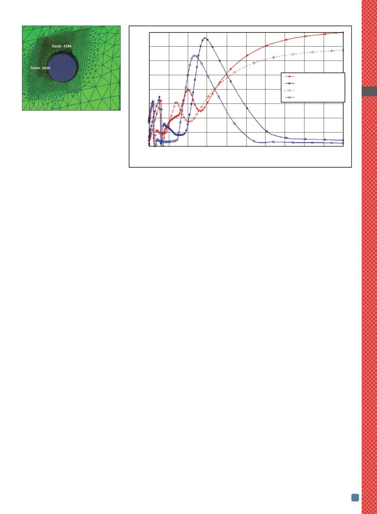
Fig. 3 —
Nodal locations on oil-hole edge
of crankshaft bearing section.
Fig. 4 —
Maximum principal stress at
node locations in Fig. 3 as a function of
spray quench time.
0 1 2 3 4 5 6 7 8 9 10
Spray time, s
800
700
600
500
400
300
200
100
0
Maximum principal stress, MPa
Node 4320, no delay
Node 4344, no delay
Node 4320, 2 s delay
Node 4344, 2 s delay