


 37 / 70

ADVANCED MATERIALS & PROCESSES •
MAY 2014
37
biocompatibility data on your finished parts.”
Once all that “stuff” is out of the way, the lifecy-
cle of a patient-specific cranial implant starts with
the patient. If someone comes to the hospital with a
skull injury, a CT or MRI scan is performed and pro-
duces a slice file similar to data used to build parts
via laser sintering.
That slice file is then sent to OPM where 3D de-
sign software is used to create an implant that pre-
cisely fits the patient’s anatomy. The implant is then
printed or “grown.” This “growing” phase is entirely
automatic—the laser-sintering system lays down a
thin layer of powder on its build platform. Guided by
the lowest slice of the implant design file, a high-tem-
perature laser melts a cross section of the implant.
When that layer is done, the build platform lowers,
and a new powder layer is distributed on top of the
old one, and the laser melts the next cross section.
The process repeats until the entire implant is built.
Laser sintering is capable of producing practically
any shape geometry to match the precise needs of in-
dividual patients.
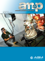
When the implant is removed from the leftover
powder (Fig. 4), it must be inspected for quality. In
addition to mechanical and analytical testing, a struc-
tured light scanner is used to do 100% line-of-sight
metrology inspection to certify its dimensional accu-
racy. Finally, the implant is shipped to the hospital.
“The total process from receiving the data to ship-
ping the implant takes less than two weeks,” accord-
ing to DeFelice. (Figs. 5 and 6).
More implant types possible
Having successfully created and obtained clear-
ance for their cranial product, OPM is making plans
to move throughout the body to use the technology.
OPM will only operate in highly regulated, high-risk
markets such as medical. “We are after critical parts,
and biomedical is the pinnacle of that,” DeFelice says.
“That means you need the right material, the right
process, the right quality system, and the right
metrology. When the patient is on the operating table
and the part shows up and doesn’t fit, you are putting
someone’s life at risk. With the first implant case,
where the implant was very large, extensive areas of
critical tissues were exposed during surgery. Every
second is critical in that situation.”
For more information:
Scott DeFelice is president and
CEO of Oxford Performance Materials (OPM), 30 South
Satellite Rd., South Windsor, CT 06074, 860/698-9300,
www.oxfordpm.com.
Fig. 1 —
A batch of implants are set up for
production. The EOSINT P 800 system can
run multiple, different designs in a single
build. All images are courtesy of Fred Smith
Associates.
Fig. 2 —
3D digital model of a cranial
implant.
Fig. 3 —
Using patient-specific 3D digital
data, the cranial implant is additively
manufactured with an EOSINT P 800
high-temperature plastic laser-sintering
system.
Fig. 4 —
The completed part
is cleaned of any
residue powder.
Fig. 5 —
Cleaned implants.
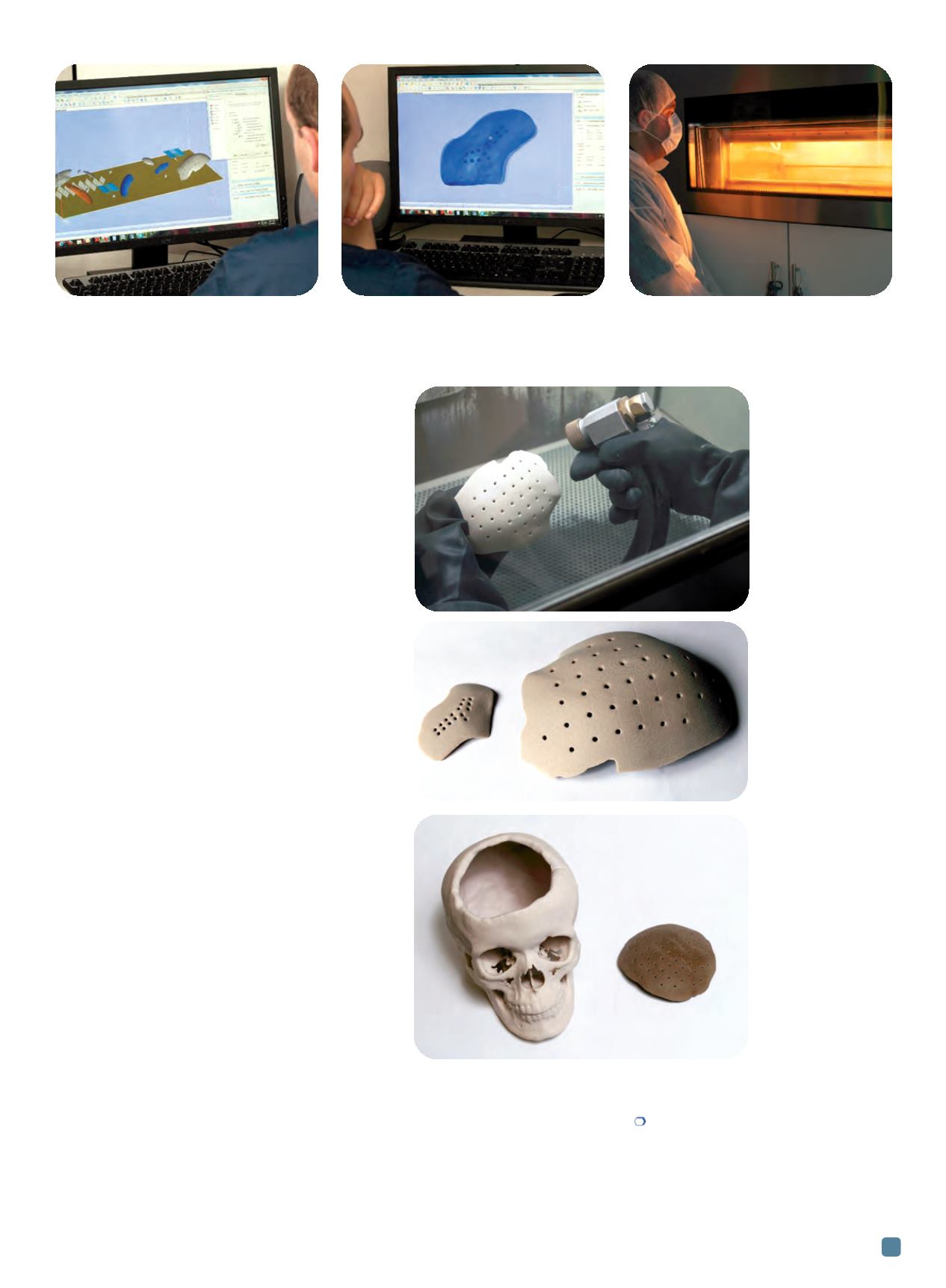
Fig. 6 —
Skull model
demonstrates how
an implant is
customized to fit the
cranial hole.