


 7 / 58

edfas.org
7
ELECTRONIC DEVICE FAILURE ANALYSIS | VOLUME 18 NO. 3
a set of voids where dark shadows in the corresponding
LOBE image (Fig. 3a) had indicated. Two of these will be
of particular interest moving forward.
As mentioned previously, to create a short between
two terminations, there must be a short path from both
terminations to the same center plate. To determine if
this scenariowere possiblewith the voids seen in acoustic
imaging, a closer examination of the waveforms used to
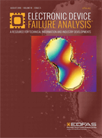
build these images is needed. The image in Fig. 4 shows
a variety of waveforms sampled from the failed part. Red
arrows on the waveform from positions 2 and 4 point
out echoes from two voids at the same position in time,
which also corresponds to depth in acoustics. These two
voids also have an unusual appearance, with dark halos
surrounding them, which increases interest in them. X-ray
inspectionwas alsoperformedon this capacitor, although
as an inspection method it is better suited for finding
large cracks beneath the terminations, where acoustic
microscopy has difficulty seeing. In this case, nothing
noteworthywas found via x-ray, so the decisionwasmade
to proceed with cross sectioning and finding out exactly
what acoustic inspection had seen.
CROSS SECTIONING AND
SEM ANALYSIS
Using the acoustic images as a guide, the failed capaci-
tor was cross sectioned to obtain a direct look at the two
suspect voids and to verify which plates they contacted.
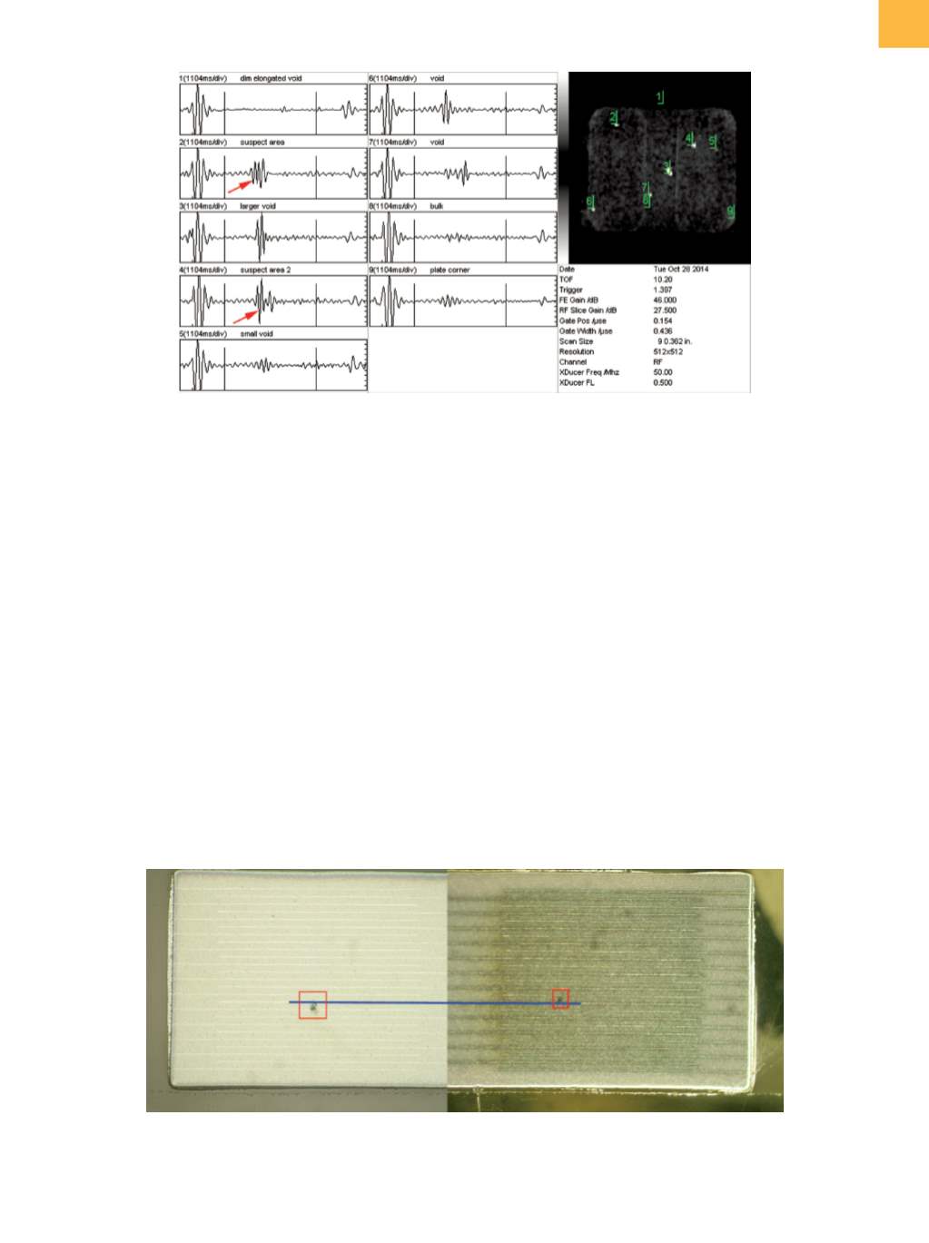
A composite optical image shown in Fig. 5 depicts both
voids, although they were not physically visible at the
same time because of the directionof the cross sectioning.
In this image, a blue line has been superimposed along
the length of one of the floating plates to illustrate that,
indeed, both of these voids make contact with the same
floating plate.
Fig. 4
Acoustic waveform capture displaying many points of interest. Red arrows highlight echoes from two voids at a nearly
identical depth from opposite sides of the capacitor.
Fig. 5
Composite optical image showing cross-sectioned views of the two voids previously identified by acoustic inspection.
The voids are highlighted with red rectangles; a blue line traces the connection to the center floating plate that these
voids share.