
A D V A N C E D M A T E R I A L S & P R O C E S S E S | M A Y / J U N E 2 0 1 7
5 8
8
TABLE 2 — REDUCTION IN RING TEMPERATURE FOR
NEW AND CURRENT HOT ZONE DESIGNS
Insulation type
Hold temperature, °F
1750 2000 2250
Standard - foil/4 layers
0.5-in. rayon felt/ring
456
544
616
New 2-in. HEFVAC
board/foil face
334
367
405
Temperature
di¯erence
122
177
211
The hold temperature is the outer temperature of the stain-
less steel ring that supports the internal insulation with the
ring radiating to the furnace cold wall, which represents the
radiation losses.
NEW BOARD HOT ZONE DESIGN
The new hot zone design is shown in Figs. 5 and 6. It
features HEFVAC boards connected in a segmented design
to form a polygon within the support ring with the boards
abutting each other to provide a strong rigid support base.
Gas cooling nozzles, graphite, and heating element supports
hold the felt in place, replacing many types of retaining pins
used in previous designs. This limits the number of retaining
pins required and thus reduces conductive losses through
the pins.
The flat boards only make direct contact with the sup-
port ring along the edge, creating a vacuum barrier between
the board and support ring, further improving thermal loss-
es. In addition, each board has a Z-shaped notch manufac-
tured on both edges for easy installation. This shape also
allows for thermal growth between boards during the heat-
ing cycle and closes any gaps, which further reduces direct
radiation loss from the interior of the hot zone to the support
ring.
The graphite heating elements are flat, segmented
graphite sections of equal dimensions. The heating elements
connect via a graphite splice joint that features a threaded
graphite bolt and nut, providing a quick and simple configu-
ration for replacement.
BOARD-TO-RING GAP THERMAL IMPROVEMENT
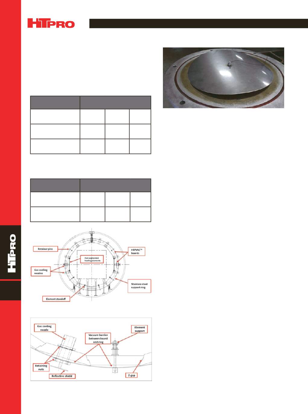
Table 3 shows an example of the new HEFVAC board’s
projected temperature improvement with a flat plate versus
a curved plate (Fig. 7), representing the shape of the support
ring (thermocouple at center of both plates). This gap further
improves the thermal loss by approximately 10%. The new
HEFVAC design is expected to reduce overall power losses
when holding at elevated temperatures by 30-40%.
~HTPro
For more information:
Real Fradette is senior techni-
cal consultant, Solar Manufacturing Inc., 1983 Clear-
view Rd., Souderton, PA 18964, 267.384.5040 ext. 1560,
real@solaratm.com,
www.solaratm.com.TABLE 3 — BOARD-TO-RING GAP TEMPERATURE
IMPROVEMENT WITH FLAT VERSUS CURVED PLATE
Insulation type
Hold temperature, °F
1750 2000 2250
2-in. HEFVAC board
with flat plate
334
367
405
2-in. HEFVAC board
with curved plate
309
332
365
Fig. 5 —
Schematic of new furnace design using HEFVAC board.
Fig. 6 —
Schematic of HEFVAC board cross sections showing
Z-shaped design.
Fig. 7 —
Board/ring vacuum gap test.
FEATURE


