


 61 / 82

A D V A N C E D
M A T E R I A L S
&
P R O C E S S E S |
M A Y / J U N E
2 0 1 7
6 1
FEATURE
11
25-mm (1-in.) diameter bar works well for evaluating furnac-
es with an HTC ranging between 250 and 650 W/m
2
K. This
covers 5-10 bar N
2
gas quench furnaces with a hot chamber.
Cold chamber quenching, higher pressure quenching, and
He gas quenching require a larger diameter 4140 bar to eval-
uate HTC throughout the quench chamber.
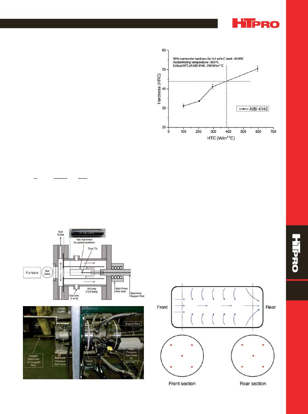
This was determined at CHTE by performing tests on a
standard gas quench unit (Fig. 2) developed by Praxair Inc.,
Danbury, Conn. Figure 3 shows the results of quenching four
25-mmdiameter bars under different gas quench conditions
(pressure and gas velocity). Hardness was measured at the
center of each bar. The plot shows the correspondingHTC for
41-43 HRC (hardness for 50%martensite for 0.40% C), desig-
nated as the critical HTC. It can be used as a measure of gas
quench hardenability. More importantly, the range of HTC
values indicates what works to understand HTC variation in
a gas quench furnace in the 250-650 W/m
2
K range. HTCwas
determined by the equation
[4]
:
where
h
is heat transfer coefficient (W/m
2
K),
P
is gas pres-
sure (Pa),
V
is gas velocity (m/s),
L
is characteristic length or
part diameter (m),
is dynamic viscosity (kg/ms),
Z
is gas
compressibility and density,
R
is gas constant (J/Kmol),
T
is
gas temperature (K),
C
p
is gas specific heat (J/kg K), and
k
is thermal conductivity (W/m
K). This equation works well
over a range of different pressures, gas temperatures, and
gas velocities. It also compareswell withdifferent Dante heat
treat simulations
[5]
.
Heat treat cycle with gas quench.
Place specimens at
desired locations in the gas quench furnace; for example,
in Fig. 4, samples are dispersed focusing on the ends of the
furnace. Test bars are austenitized at the appropriate tem-
perature (e.g., 850°C for AISI 4140) and quenched, recording
quench conditions (gas temperature, furnace pressure, and
gas velocity).
Hardness measurements.
A slightly larger than 13-mm
(0.5-in.) disc is taken from the center of each specimen so
one side is from a transverse cut at the center of the bar and
hardness is measured at the center of the disc.
Fig. 2 —
Schematic of Praxair gas quench system shown with a
25-mmdiameter × 100-mm long (1 × 4-in.) specimen.
Fig. 3 —
Hardness results from various surface HTC settings in
the standard quench system for 25-mm (1-in.) diameter AISI 4140
steel.
Fig. 4 —
Gas flow direction and sample location in the furnace.
h
=
k
L
0
.
023
(
PVL
ZRT
)
0
.
8
(
C
P
k
)
0
.
33