


 60 / 82

FEATURE
A D V A N C E D M A T E R I A L S & P R O C E S S E S | M A Y / J U N E 2 0 1 7
6 0
G
as quenching is widely used in the aerospace and au-
tomotive industries for mediumand high hardenabil-
ity steels
[1]
. However, two areas of uncertainty in gas
quenching include hardenability measurement and cooling
characteristics of vacuum or non-vacuum furnace quench
chambers. Twoquestions arise regardinghardenability: How
does alloy variability within a steel grade impact hardening
characteristics? And howdoes it alter themartensite percent
versus depth curve on carburized and direct hardened com-
ponents? Questions with respect to cooling include: What
does a “10 bar nitrogen quench” furnace mean? And what
is the heat transfer coefficient (HTC) at the surface of a part
in different areas of the furnace? The Center for Heat Treat-
ing Excellence (CHTE) at Worcester Polytechnic Institute
(WPI) developed methods to evaluate steel hardenability
on medium and high hardenability steels in a standard gas
quench test and to evaluate HTC variation within a furnace
gas quench chamber
[2]
.
The method for evaluating medium and high harden-
ability steels in a gas quench uses a Grossman-like harden-
ability approach and establishes a critical HTC for a 25-mm
(1-in.) diameter specimen. The test can be modified for larg-
er diameters, which is required for high hardenability steels.
Critical HTC is defined as the surface heat transfer coefficient
required to obtain 50% martensite in the center of the 25-
mm specimen. Understanding both the approximate range
of HTCs in a given furnace and the critical HTC for the steel
being processed enables using both tests in tandem to pro-
vide excellent furnace HTCmapping for any load.
PROPOSED GAS QUENCH FURNACE
EVALUATION PROCEDURE
Linking the gas quench steel hardenability test with the
furnace quench capability test is best explained by following
the procedure used to determine furnace quench capability
and uniformity. Cylindrical test bars are used, with the num-
ber and location of bars varying according to how essential
it is to understand cooling uniformity at all parts in the load.
The bars can evaluate standard loading or be used without
any other parts. Hardness at the center of the bar is ultimate-
ly correlated to a surface HTC. The relationship is established
using either the standard gas quench hardenability method
or a heat treat simulation code such as Dante, from Dante
Solutions, Cleveland
> @
.
Heat treat simulation steps are as follows:
1. Estimate HTC range for furnace to be tested.
2. Select proper sample size and alloy.
3. Carry out heat treat cycle with gas quench.
4. Measure hardness.
5. Establish HTC for each specimen location.
Estimate HTC range for furnace to be tested.
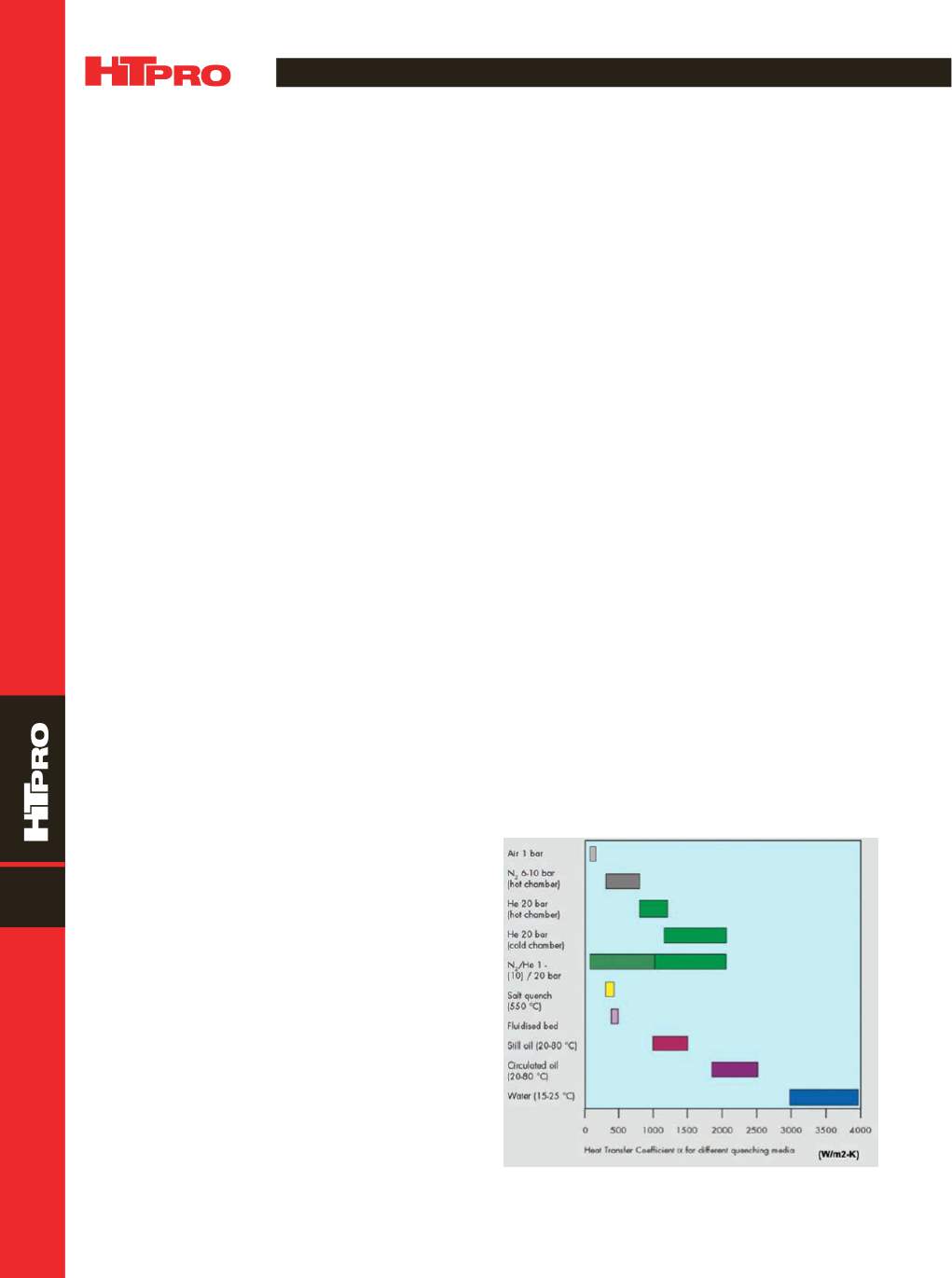
Figure 1
shows that gas quenching in vacuum furnaces, whether for
direct hardening or carburizing, provides surface heat trans-
fer coefficients (
h
, or HTC) ranging between 100 and 2000
W/m
2
K.
Select proper sample size and alloy.
The heat treater
or final user should select the alloy for a critical component
and then select the proper size for that alloy. The correct size
is that which will provide a range of percent martensite at
the center (ideally between 50%and 90%). For carbon steels
with 0.40%C, such as AISI 4140 and 4340, this results in hard-
ness of 42-50 HRC at the center of the bar. For grade 4140, a
*Member of ASM International
GAS QUENCHING: LINKING STEEL HARDENABILITY
AND FURNACE COOLING CAPABILITY TESTS
New methods evaluate steel hardenability in a standard gas quench test and HTC variation
within a furnace gas quench chamber.
Yuan Lu* and Richard Sisson, Jr., FASM,* CHTE,
Worcester Polytechnic Institute, Mass.,
and Michael Pershing,*
Caterpillar Inc., Peoria, Ill.
Fig. 1 —
Heat transfer coeicients for dierent quenching
media
[1]
.
10