
A D V A N C E D M A T E R I A L S & P R O C E S S E S | M A Y / J U N E 2 0 1 7
5 6
FEATURE
6
C
urrent vacuum furnace hot zone designs include
all-metal shielding, ceramic fiber (kaowool), and
graphite fiber, foil, and board combinations. Typically,
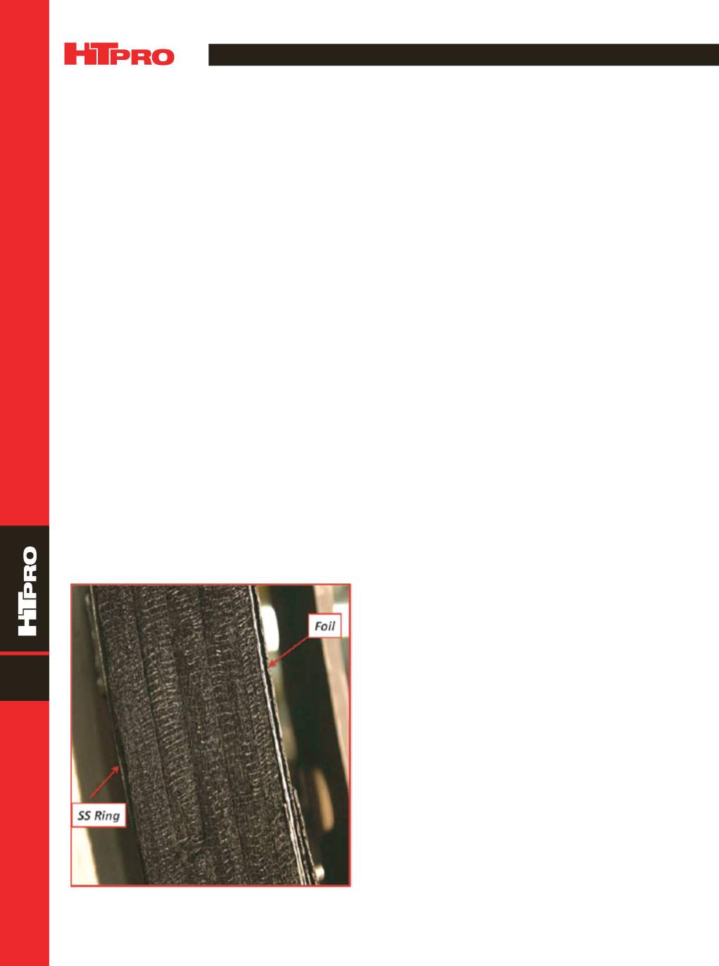
a stainless steel ring structure supports the insulation pack-
age within the hot zone (Fig. 1). Energy studies shows that
the all-metal hot zone is the least efficient, requiring a larger
and more expensive power supply when operating at tem-
peratures around 1150°C (2100°F). All-metal designs usually
include a combination of thin molybdenum and stainless
steel shields. These hot zones typically offer better vacuum
levels and super clean work compared to other options.
However, they are more expensive, 30% less efficient, and
usually last about half the time of other insulated hot zones.
Ceramic fiber provides superior insulating properties,
but it tends to absorb substantial amounts of water vapor
when opened to air. This leads to longer evacuation times,
especially during high-humidity days. In addition, ceramic fi-
bers shrink at high temperatures and create gaps within the
support ring that result in additional energy losses.
The majority of all-purpose vacuum furnaces manufac-
tured today use a combination of graphite felt and foil and
graphite felt and board. For example, most modern furnaces
contain four 0.5-in. thick layers of graphite felt with either a
graphite foil hot face or a rigid graphite board hot face (pri-
marily used in high-pressure gas quench furnaces). Graph-
ite felt has a tendency to absorb water vapor, but not to the
same extent as ceramic fibers. Care must be taken to keep
the furnace closed as much as possible. With correctly sized
vacuum pumps and proper maintenance and operating
practices, this type of furnace is capable of producing very
clean work.
Recently, Solar Manufacturing and Solar Atmospheres
compared a new graphite board with current products.
The new board (a standalone insulation package produced
by Graphite Machining Inc., Topton, Pa.) is a 2-in. thick,
high-density compressed graphite fiberboard sealed with a
proprietary graphite polymer tominimize porosity andmois-
ture absorption.
COMPARISON OF POWER LOSS
AND INSULATION
To conduct experimental work, a standard vertical
laboratory-type vacuum furnace (12-in. diameter by 18-in.
high) was modified with an extension piece placed on the
main chamber (Fig. 2). The extension provided a space to
add thicker insulation packages to the top of the furnace
hot zone. The temperatures of the furnace hot zone and
outer stainless steel lid were measured using calibrated
Inconel thermocouples at three different stabilized furnace
temperatures.
The temperature of the outer stainless steel lid rep-
resents the temperature of support ring “A” (Fig. 3) adjacent
to the furnace cold wall “B.” The major thermal loss in a vac-
uum furnace stems from the ring radiating energy to the fur-
nace coldwall. Other losses via hearth pins and nozzle direct
radiation losses are not included in the analysis.
Total energy radiated by a black body is given by the
Stefan-Boltzmann law:
P
=
HV
A
(
T
4
–
T
c
4
)
where
P
is net radiated power,
H
is emissivity of the radiating
surface (0.55 for stainless steel),
V
is the Stefan-Boltzmann
constant (5.670367
u
10
−8
W
m
2
K
−4
),
A
is the radiating sur-
NEW DEVELOPMENTS IN VACUUM FURNACE HOT ZONE DESIGN
A novel hot zone design featuring new graphite boards reduces heat loss
and improves overall hot zone power requirements.
Real J. Fradette,* Virginia Osterman,* and William R. Jones, FASM*
Solar Atmospheres Inc., Souderton, Pa.
*Member of ASM International
Fig. 1 —
Graphite hot zone in which stainless steel support ring
holds insulation package in place.


