


 30 / 54

A D V A N C E D M A T E R I A L S & P R O C E S S E S | J A N U A R Y 2 0 1 7
3 0
encounters the interface between two
materials, a portion is reflected back to
the transducer as an echo signal, while
another portion is transmitted across
the interface and travels deeper into
the sample, where it may encounter an-
other interface and send back another
echo signal. Any interface between a
solid and air or another gas is an excep-
tion as at these interfaces, nearly all of
the ultrasound is reflected as an echo
signal. None is transmitted across the
interface. The echo signal from a solid-
to-air interface has the highest possible
amplitude and therefore appears bright
white in monochrome acoustic images.
The color of solid-to-solid interfaces de-
pends on the physical characteristics of
the two materials at the interface, and
ranges from light gray (high amplitude)
to dark gray (low amplitude).
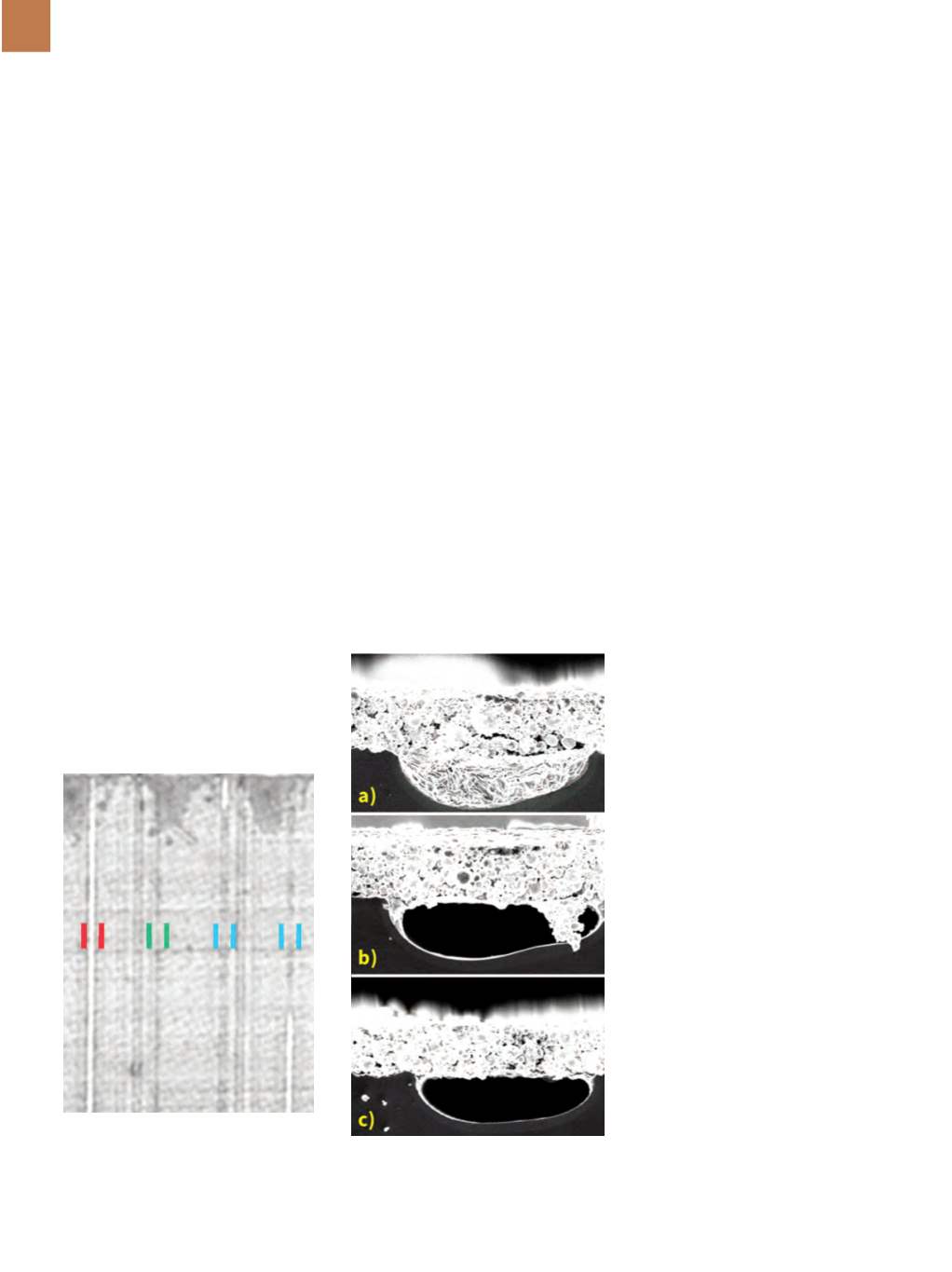
One region of the cell was acous-
tically imaged (Fig. 2). Four equally
spaced trenches, all of which should be
filled with aluminum paste, are marked
by colored bars. Linear features parallel
to the trenches are at a different depth
and are not trenches.
The left trench marked by red bars
is bright white, meaning that it is voided
for the entire length shown here. During
screen printing, the trench depth is not
completely filled with aluminum paste.
The void that lies between the die and
paste prevents electrical contact. The
trench marked by green bars is dark—
meaning it is completely filled. This is
the desired condition that allows elec-
trical contact between the silicon and
aluminum paste. The two trenches
marked by blue bars are partially filled
and partially voided.
Throughout the cell, comparing
the dark vertical features in the elec-
troluminescence image in Fig. 1 to the
trenches acoustically imaged in Fig. 2
reveals that only some of the acous-
tically visible voids also appear in the
electroluminescence image. The cell
was next sectioned through some of the
trenches, and the trench cross-sections
were viewed by a scanning electron mi-
croscope (SEM). Typical results are seen
in Fig. 3.
In Fig. 3a, the rounded trench pro-
file in the SEM image shows that the
trench is completely filled by alumi-
num paste. Dark regions in the trench-
es in Fig. 2 would appear much like
this in cross-section. In this figure, the
aluminum layer bonded to the back-
side surface lies just above the trench.
Electrical contact in this portion of this
trench is acceptable.
In Fig. 3b, the only area of the
trench that has been filled is at the
right. The efficiency of such a small fill is
unknown, but it is likely to be limited. In
Fig. 3c, the entire trench is voided and
there is likely no electrical contact. In an
acoustic image, this trench (along with
that in 3b) would appear bright white.
CONCLUSION
Next steps in this research will in-
clude precise characterization of the
relationship between the acoustic ap-
pearance of a trench and the degree of
electrical contact between the alumi-
num paste and the solder. This infor-
mation will permit better control over
PERC production, maximize cell effi-
ciency, and make it possible for PERC
crystalline silicon solar cells to fulfill a
prediction by the International Technol-
ogy Roadmap for Photovoltaic that they
will capture 45% of worldwide market
share by 2024.
~AM&P
For more information:
Steve
Martell is manager, advanced applica-
tions support, Sonoscan Inc., 2149 E.
Pratt Blvd., Elk Grove Village, IL 60007,
847.437.6400,
info@sonoscan.com,
www.sonoscan.com.
*C-SAM is a registered trademark
of Sonoscan Inc.
Fig. 3 —
SEM images of cross sections
through filled, partly filled, and unfilled
trenches.
Fig. 2 —
C-SAM imaging illustrates the
difference between filled (dark) trenches
and trenches that are partly or entirely
unfilled (white).