
1 9
A D V A N C E D
M A T E R I A L S
&
P R O C E S S E S | J A N U A R Y
2 0 1 6
T
he Orion Multipurpose Crew Ve-
hicle is NASA’s vehicle for hu-
man exploration of deep space.
Its maiden voyage—Exploration Flight
Test 1—was an unmanned flight de-
signed to test the vehicle’s main sys-
tems, which launched from Kennedy
Space Center on December 5, 2014. The
trip included two earth orbits followed
by reentry at approximately 20,000mph,
subjecting the heat shield to 4000°F.
Landing and recovery took place in the
Pacific Ocean. Among the technology
advancements included on Orion were
additively manufactured (AM) vents
used as air passages for the unpressur-
ized portions of the spacecraft.
Exploration Flight Test 1 used four
vent assemblies to equalize pressure
between the unpressurized portions of
the spacecraft and the external environ-
ment. The assemblies contained the AM
housings and integral screens as well as
two additional screens that were weld-
ed on. Each assembly was then bolted
into the vehicle using three mounting
flanges. Complete assemblies were
roughly the size of a 1-liter water bottle.
Initial design called for a wire
mesh to be welded into the housing.
Multiple screens were needed for re-
dundancy, and a cylindrical shape was
desired due to space limitations inside
the vehicle. Because this initial design
proved difficult to produce, additive
manufacturing was proposed.
PARTS MANUFACTURING
Parts were additively manufac-
tured from a nickel alloy (Inconel 718)
using the vendor’s recommended pro-
cedure. (Note that this was before in-
dustry specification ASTM F3055 was
available for use.) Each build cycle con-
tained one part and corresponding test
coupons. Parts were additively manu-
factured, stress relieved, hot isostati-
cally pressed (HIP’d), solution treated,
and aged. This corresponds with ASTM
F3055, Class D, although the processing
parameters were not identical. Machin-
ing was performed on some surfaces
to remove the support structure or to
provide a smooth surface for fastener
installation. Welding was performed
using industry specification AWS D17.1.
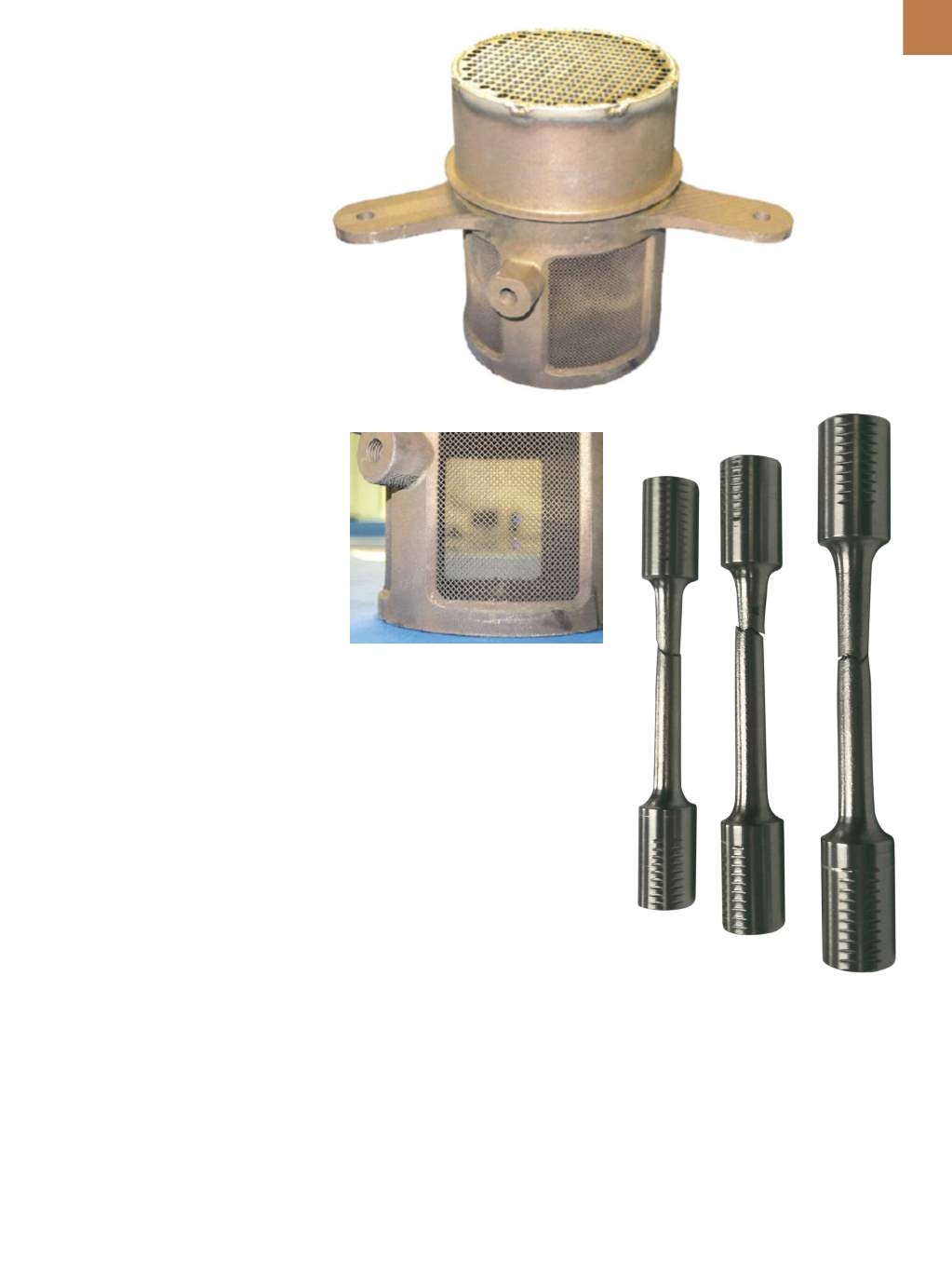
Fig. 1 —
Complete passive vent
assembly. The mesh on the top
was welded onto the additively
manufactured housing.
Fig. 2 —
Close-up of passive vent, showing
AM screen details.
Fig. 3 —
Representative tensile specimens
after testing.
Development welds were performed
and examined to determine sufficiency
of the weld schedules.
DEVELOPMENT TESTING
Three witness coupons were print-
ed with each part, comprising tensile
specimens in the
x, y,
and
z
orientations
(where
x
and
y
are on the build plane
and
z
is in the build direction). Speci-
mens were manufactured as cylinders,
machined to a 0.25-in. test diameter,
and tested per ASTM E8 at room tem-
perature. All specimens met ASTM
F3055 Class D requirements and were
within 15% of specification values. Fig-
ure 3 shows typical specimens.
Three tensile specimens were in-
tentionally not HIP’d for comparison.
These non-HIP’d specimens exhibited
approximately the same strength as the
HIP’d specimens, suggesting that the
HIP process may not provide a signifi-
cant strength benefit.
Microstructural evaluations were
also performed. Overall, specimens ex-
hibited very little porosity. Grains were
finer near the edges than in the center
of the coupons. Specimens were free of
Laves phase, an undesirable interglob-
ular phase
[1,2]
. A typical microstructure
is shown in Fig. 4 (50
×
magnification).


