


 55 / 78

D
irect write technology is an innovative and economi-
cal materials deposition process that integrates con-
ductive traces, antennas, circuits, and sensors onto
components or embeds them within structures. The tech-
nology was initially developed under the Defense Ad-
vanced Research Projects Agency’s (DARPA) Mesoscopic
Integrated Conformal Electronics (MICE) program by
Stony Brook University, N.Y., and its partners. The process
has been in development since 2002 for use in aerospace,
military, and energy markets.
Direct write technology basics
The direct write process uses a
small torch and aperture system to
fabricate patterned material traces and
coatings onto complex surfaces. The
print head generates a highly colli-
mated, well defined particle stream
capable of fabricating low profile, fine
feature conductor patterns and ce-
ramic dielectrics onto critical compo-
nents, as shown in Fig. 1.
Patterns are printed with typical
feature sizes ranging from 250 µm to
3 mm wide and roughly 50 µm thick
(thinner and thicker deposits are pos-
sible). A7-axis robotic system ensures
pattern placement accuracy and man-
ufacturing consistency afforded by 20 µm tool path repeata-
bility. The process enables a wide range of materials to be
deposited including ceramic dielectrics, high quality copper
and precious metal conductors, sensor alloys, and functional
ceramic oxides. The process is also compatible with most
substrate/component materials including polymer laminates,
fiber-filled composites, and metallic structures.
Advantages include the ability to conformably print
onto 3D geometries, operation in standard atmosphere (no
vacuum or inert atmosphere required), and robust deposits
that withstand high temperatures (>1000°C) and are both
erosion resistant and strain tolerant. Direct write printing is
used to construct aerospace components by enabling em-
bedded circuitry, and in high temperature propulsion sys-
tems by incorporating diagnostic sensors (temperature and
heat flux) for structural health monitoring. The technology
has also been used to integrate UHF/VHF/L-Band antennas
into air and space vehicle components for advanced com-
munications and signals intelligence.
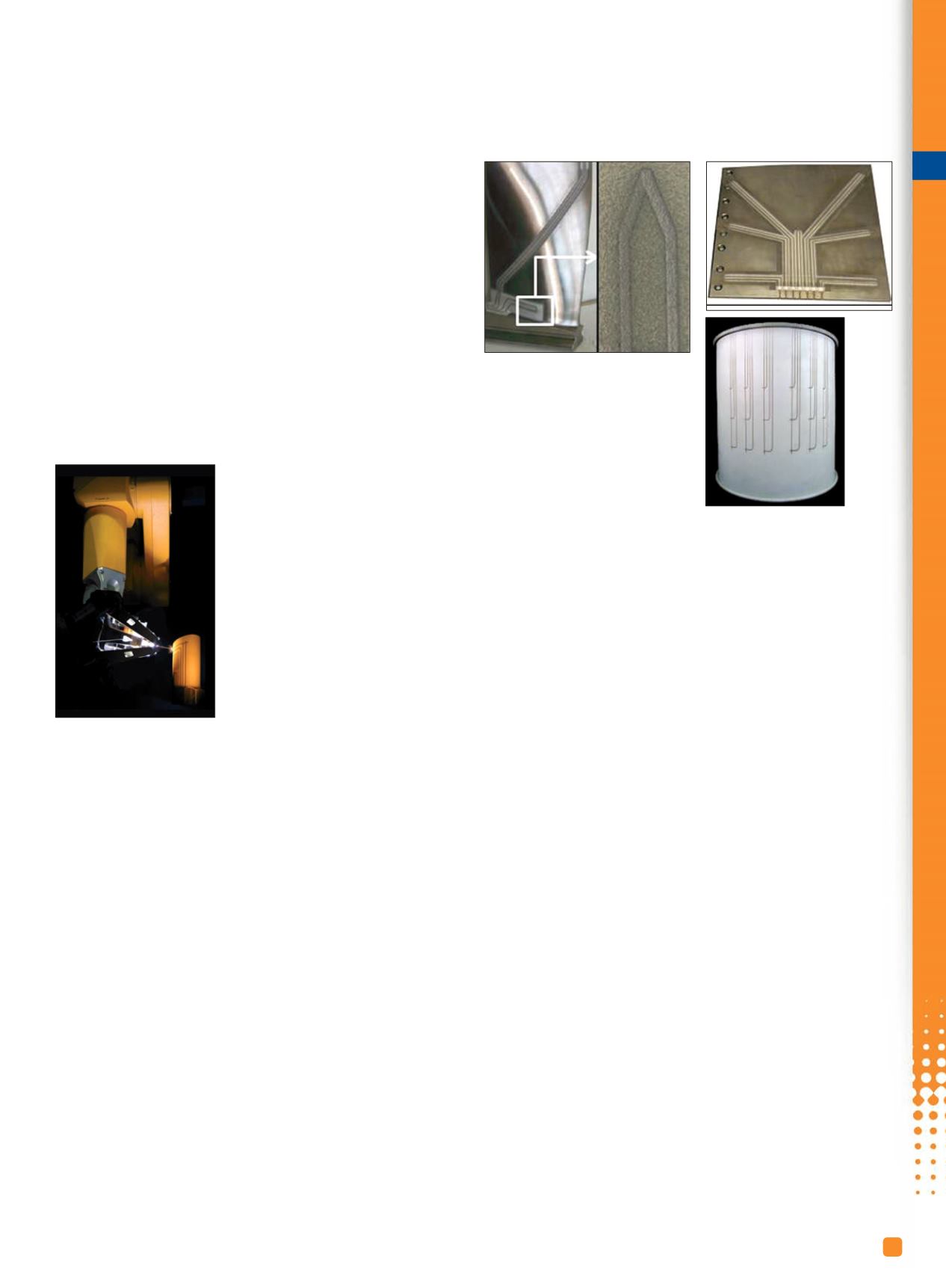
Printed thermocouple sensors
Many types of thermocouple systems can be fabricated
to provide integrated sensing for operational components.
A variety of NIST standard alloys
including types T, E, K, and N as
well as precious metals can be
used to achieve the requisite performance and durability.
The latter have been tested in oxidizing environments at
1000°C for 8000 hours, exhibiting >4% drift. Thermocou-
ple sensors (TCs) are printed directly and conformally onto
structures and embedded within protective coatings if nec-
essary. Leads are routed to convenient locations for signal
acquisition. TCs have been printed onto a range of materi-
als including polymers, fiber composites, metals, and
ceramic matrix composites (Fig. 2). Temperature measure-
ments provide information relative to the materials re-
sponse in specific thermal environments and offer a means
of monitoring the component via closed-loop control.
Through interactions with OEM partners, sensors were
successfully used in gas turbine engines at full load as well
as in hypersonic scramjet engine tests.
Benefits of using printed thermocouples to measure
temperature include:
• Direct printing onto 3D components or polymer
laminates for composite integration
• Low profile design, generally 50 µm thick
• Repeatable installation using robotics
• Embedding within thermal barrier coatings or other
protective surface treatments
• Creation of “smart” components for health
monitoring and assessment
• Accuracy improvement of prognostic models by
measuring part temperature
Printed heat flux sensors
Heat flux sensors were developed based on multilay-
ered thermopile architectures to supplement temperature
measurements in monitoring engine transients for ad-
vanced hypersonic scramjet control systems. Extensive
testing was performed at the Air Force Research Lab
(AFRL) under an SBIR Phase II contract, within the com-
bustor at simulated Mach 5 flight conditions, where gas
temperatures often exceed 1900°C.
i
T
S
S
e
5
ADVANCED MATERIALS & PROCESSES •
NOVEMBER-DECEMBER 2014
55
Smart Deposition Process Integrates
Sensors and Heaters into Coatings
Jeff Brogan
MesoScribe Technologies Inc.
Setauket, N.Y.
Fig. 1 —
Sensor
application using direct
write technology.
Fig. 2 —
Thermocouples created
with direct write. Instrumented
compressor blade (above), TC array
onto a metallic structure (above
right), TC array onto cylindrical
component (right).