


 19 / 70

A D V A N C E D
M A T E R I A L S
&
P R O C E S S E S |
S E P T E M B E R
2 0 1 6
1 9
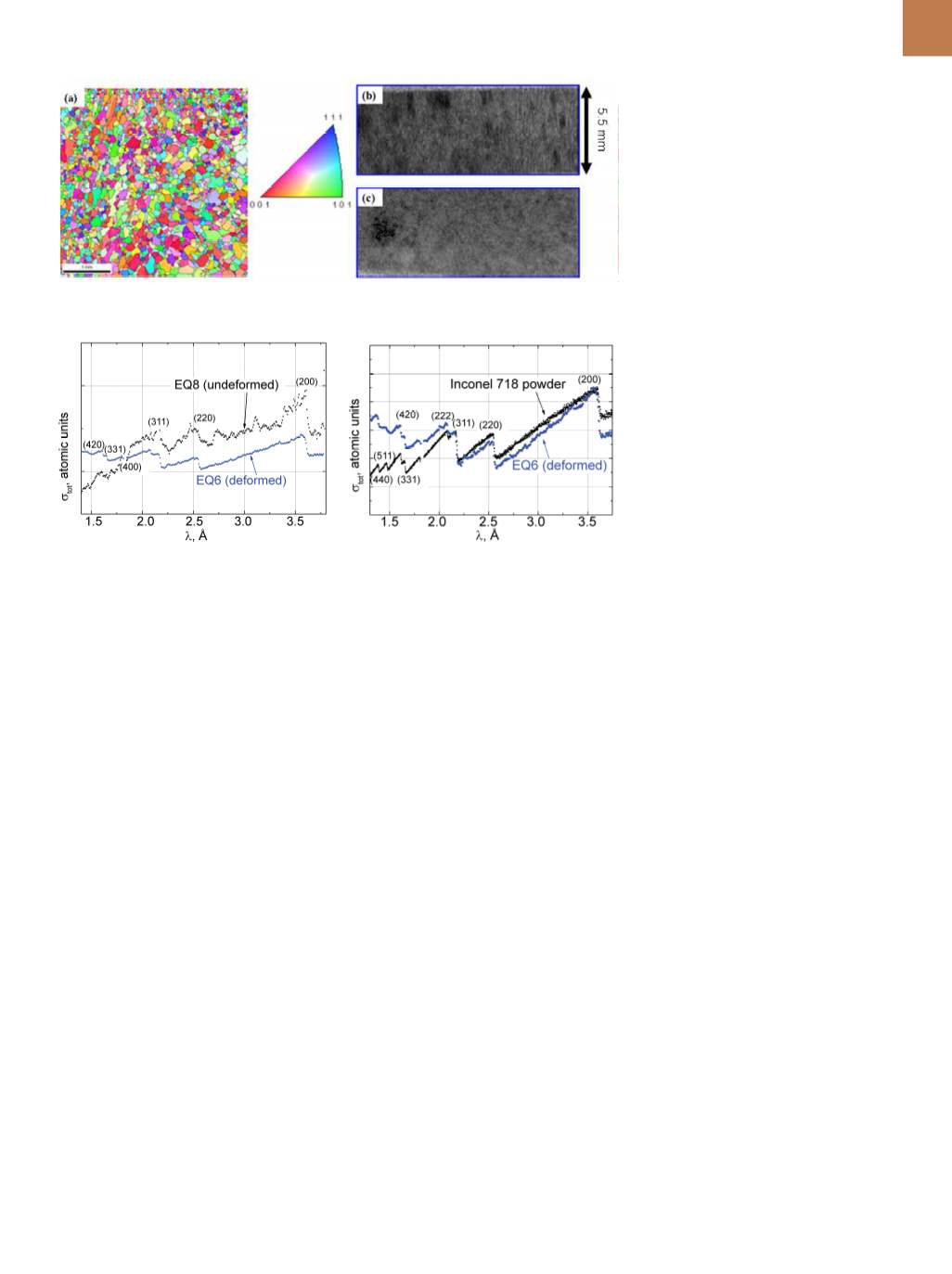
Fig. 3 —
(a) Electron back scatter diffraction map and (b) neutron radiograph before compres-
sion of equiaxed sample; (c) neutron radiograph of equiaxed sample after compression.
neutron diffraction strain mapping and
ESBD. Bragg edge radiography provides
grain orientation average over the thick-
ness of a sample, with differences in neu-
tron transmission due to the Bragg edge
scattering at wavelengths specific to
each crystal lattice plane. This technique
effectively measures crystal plane orien-
tation, assesses single crystal quality,
and quantifies Bragg edge shifts, which
are indicative of average strain through
the thickness of the material
at a neu-
tron pulsed source such as the SNS.
While interest in additive manufac-
turing is increasing, the role of process-
ing variables onmicrostructure is still not
sufficiently understood to enable pre-
dictive finite element modeling design.
Experimental measurements were per-
formed at the SNS Vulcan diffractometer,
which revealed localized reorientation
and refinement of grains due to compres-
sion. These preliminary results highlight
the potential of TOF neutron radiography
to contribute to the understanding of
AM materials characteristics. However, a
pixel-by-pixel study would provide more
detailed information. Further devel-
opments are aimed at enabling a pix-
el-by-pixel study, with potential spatial
resolution on the order of tens ofmicrons
and modeling of the Bragg edges to fur-
ther understand microstructure and its
evolution.
~AM&P
ACKNOWLEDGMENT
The team thanks M. Frost and
H. Skorpenske for setting up the detec-
tor at the SNS beamlines. Resources at
the High Flux Isotope Reactor and Spall-
ation Neutron Source, U.S. DOE Office
of Science User Facilities operated by
ORNL, were used in this research. This
research is also sponsored by the Lab-
oratory Directed Research and Devel-
opment Program of ORNL, managed by
UT-Battelle LLC, for DOE.
Formore information:
Hassina Bilheux
is neutron imaging lead instrument
scientist for the HFIR CG-1D and SNS
VENUS beamlines, Oak Ridge National
Laboratory, 1 Bethel Valley Rd., Oak
Ridge, TN 37831,
bilheuxn@ornl.gov,
865.384.9630, neutrons.ornl.gov.
Fig. 4 —
Bragg edge mapping of as-fab-
ricated (undeformed) and compressed
(deformed) EQ8 and EQ6 equiaxed sam-
ples, respectively. Bragg edges of unde-
formed sample show presence of preferred
grain orientation (bumps between Bragg
edges), whereas Bragg edges of deformed
sample are similar to Inconel 718 powder,
indicating a local change in grain orien-
tation due to compression. Technique
provides pixel-by-pixel mapping of prefer-
ential grain reorientation.
Fig. 5 —
Bragg edge mapping comparison of
Inconel 718 powder and equiaxed deformed
sample EQ6.
(EBSD) grain orientation map for one of
the equiaxed samples.
After solidification and removal
from the stainless steel base plate,
samples were compressed 13% and
compared with their uncompressed
counterpart using Bragg edge radi-
ography (Fig. 3). Before compression,
grains with the same orientation are
visible in the radiograph (Fig. 3b), but
they realign preferentially due to com-
pression (Fig. 3c). These results are also
reflected in Bragg edge image analy-
sis (Fig. 4). Before compression, Bragg
edges are not as pronounced as in the
powder sample despite the fact that the
samples were printed with no preferred
grain orientation. A trend similar to that
in the powder sample (Fig. 2) might be
expected. The presence of “bumps” in
the Bragg edges of the uncompressed
sample EQ8 is likely due to the presence
of grains with a preferred orientation in
the sample (Fig. 3b).
After compression, sample EQ6 has
greater similarity to the Inconel powder
sample (Fig. 2), indicating the absence
of preferred crystallite orientation—as
if sample grains reoriented during com-
pression. A direct comparison between
Inconel powder and the deformed EQ6
sample is shown in Fig. 5. Bragg edges
are similar for both, while the (200) edge
for powder is higher, illustrating that the
(200) orientation is more predominant
in the deformed sample. Also, the (511)
Bragg edge in the deformed sample is
poorly defined, which is likely due to the
preferred grain orientation in the sam-
ple rather than instrument wavelength
resolution, because all measurements
were performed at the SNS Vulcan dif-
fractometer under the same beam optic
configuration.
CONCLUSIONS
ORNL has recently implemented
neutron radiography based on detect-
ing Bragg edge features to complement